4.9 IGV
TheIGVassemblyconsistsofmovablevanesandamotor.TheIGVassemblyisavariable-angleguidingdevicethatis
usedtocontrolcapacityatlow-loadconditions.TheIGVpositioncanvarybetween0degrees(closed/perpendicular
toflow)and90degrees(open/paralleltoflow).ThevaneangleisdeterminedbytheBMCCandcontrolledbythe
SerialDriver.TheSerialDriveruses+15VDCtocontroltheIGVsteppermotor.
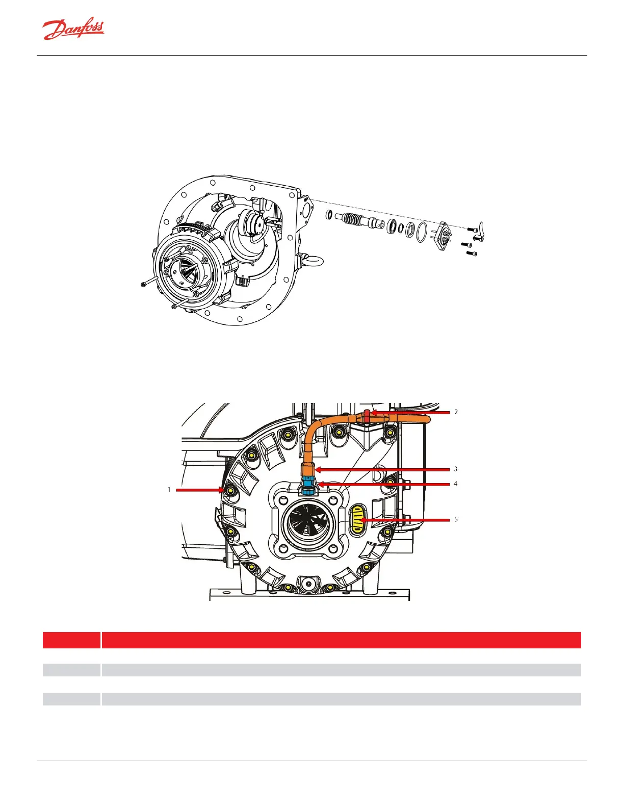
Figure 4-41 IGV Assembly
4.9.1 IGV Connections
RefertoFigure4-42IGVConnectionsforthelocationoftheIGVconnections.
Figure 4-42 IGV Connections
Table 4-14 IGV Components
No. Component
1 TheIGVassemblyisboltedtothecompressorhousing.
2 ThecompressorcontrollercableisheldtotheIGVMotorfeedthroughbythecableclip.
3 Thecompressorcontrollercablecontinuesontothesuctionpressure/temperaturesensor.
4 Thesuctionpressure/temperaturesensorisconnectedtotheIGVHousing.
5 IGVPositionIndicator.
Page 82 of 294 - M-SV-001-EN Rev. H 1/23/2023