Table 4-10 Solenoid Coil Resistance Ranges
Voltage Power Resistance
24V 9.3W
56.25Ω–68.75Ω
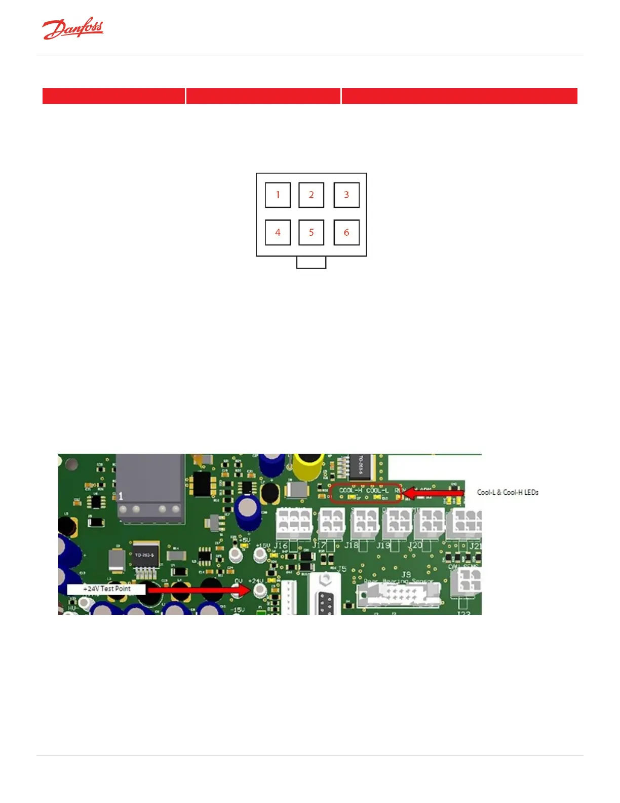
Figure 4-32 Compressor Cooling Solenoid Coil Cable Connector
4.6.3.2 Output Voltage to Solenoid Coils
1. RemovetheServiceSideCover.RefertoSection4.1.3.1ServiceSideCoverRemovalandInstallationon
page54.
2. ThecompressormustberunningandmakeacalltoenablethecoolingsolenoidcoilsfortheLEDsto
turnon.TheSMTCoolingModewillindicate"inverter,""motor,"or"motorandinverter"whenthe
softwareissendingthesignaltothecoils.
3. ToensuretheSerialDriverisprovidingpowertothesolenoids,lookfortheCool-LandCool-HLEDson
theBackplane.RefertoFigure4-33Backplane-CoolLEDsand+24VTestPoints.
4. Todetermineif24VDCispresentatoneorbothsolenoidcoils,useamultimetertotestthebacksides
ofpins1&3andpins5&6ofthecoolingsolenoidcoilsWHILEtheyareenergized.RefertoFigure4-32
CompressorCoolingSolenoidCoilCableConnector.
Figure 4-33 Backplane - Cool LEDs and +24V Test Points
4.6.3.3 Cooling Path Blockage Inspection
1. Isolatecompressorpower.
2. Isolatethecompressorandrecovertherefrigerantaccordingtoindustrystandards.RefertoSection3.1
RefrigerantContainmentonpage41.
3. RemovetheServiceSideCover.RefertoSection4.1.3.1ServiceSideCoverRemovalandInstallationon
page54.
4. Removetheactuators,solenoids,andorifices.
Page 74 of 294 - M-SV-001-EN Rev. H 1/23/2023