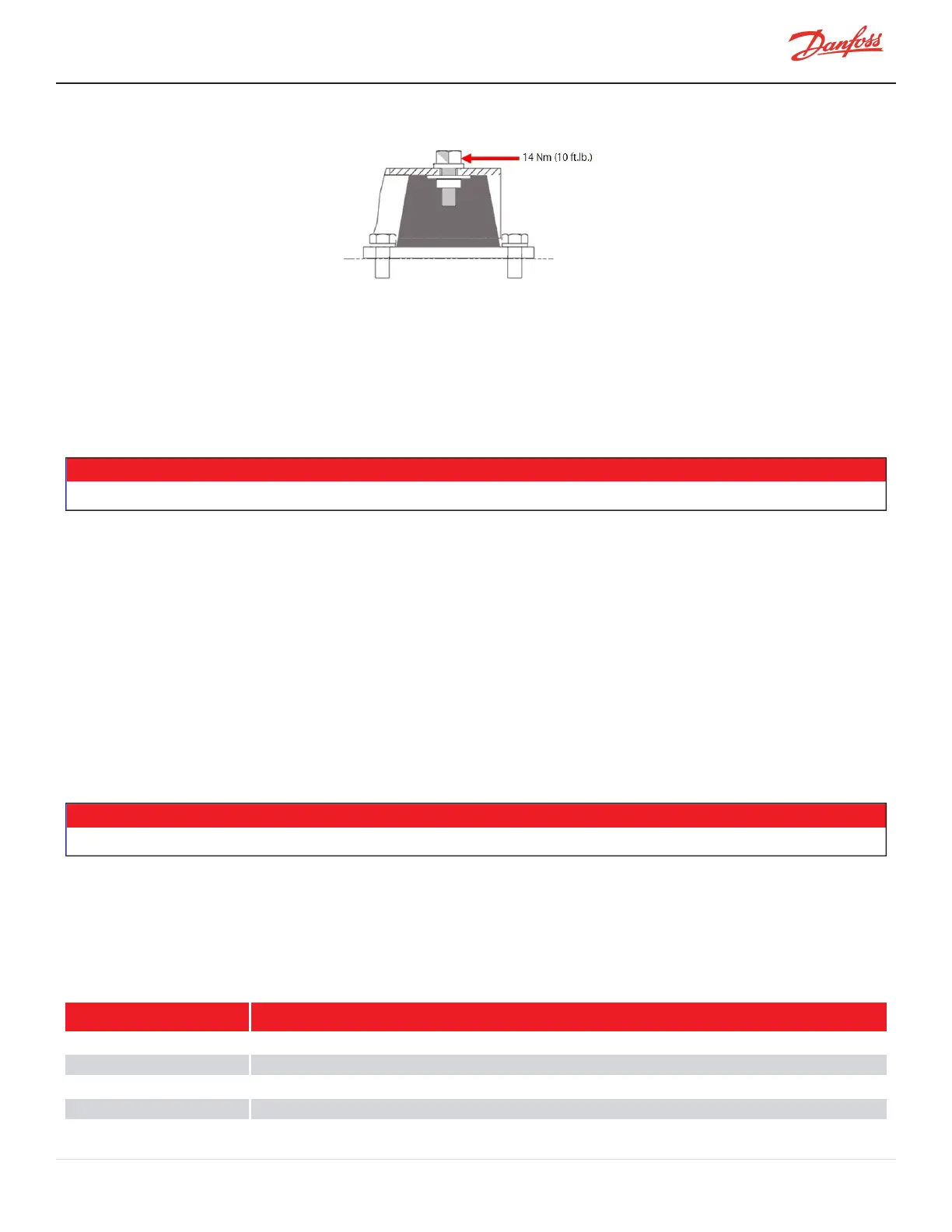
Figure 3-2 Compressor Mounting Fasteners
15. Torquethemotorcoolinglineconnection(Nut)to11Nm(8ft.lb.).
16. RemovetheServiceSideCover.RefertoSection4.1.3.1ServiceSideCoverRemovalandInstallationon
page54.
17. InstalltheI/Ostrainrelieftothecompressorhousing.
18. ConnectthecompressorI/OcabletotheBackplaneI/Oconnector(J7).
19. InstalltheServiceSideCover.RefertoSection4.1.3.1ServiceSideCoverRemovalandInstallationon
page54.
• • •DANGER! • • •
EnsurethatelectricalpowerisisolatedfromtheACmainscablesbeforehandlingthecables.
20. RemovetheMainsInputCover.RefertoSection4.1.1.1MainsInputCoverRemovalandInstallationon
page52.
21. ConnectthecableglandthatsecurestheMainsInputcableconduittotheMainsInputbracket.
22. InstalltheMainsInputgroundwiretothegroundpostandtorquethetopnutto10Nm(7ft.lb.).
23. AttachtheACmainscablestotheterminalsandtorquetospecification.
l
TTS300/TGS230Compressors-20Nm(15ft.lb.)
l
AllCompressors(excludingTT300/TG230)-21Nm(15ft.lb.)
24. InstalltheMainsInputCover.RefertoSection4.1.1.1MainsInputCoverRemovalandInstallationon
page52.
25. Leaktestandevacuateinaccordancewithstandardindustrypractices.
26. Returnthecompressortonormaloperation.
Changestothecompressorsoftwaresettingsmaybenecessarytoalignwiththechillerrequirements.
3.4 Compressor Replacement Considerations for Motor Cooling Adapter
ThehousingconnectionsealisanISOstandardO-ringsealandtheexternalpipeworkconnectionisanORFS.In
addition,thelinesizeis1/2inchforallmodelsandthefittingincludesabuilt-in(removable)strainer.
RefertoFigure3-3MotorCoolingFittingonpage44.
Table 3-1 Cooling Adapter Detail
Component Notes
Body IncludesbothO-rings-BodytocompressorhousingthreadisM16x1.5.
Strainer -
BlankingDisk -
1/2"BrazeSleeve Steelforallconnecting1/2coppertube
M-SV-001-EN Rev. H-1/23/2023 Page 43 of 294