4. RemovetheMotorBusBars.RefertoSection4.23.5MotorComponentsRemovalandInstallationon
page196.
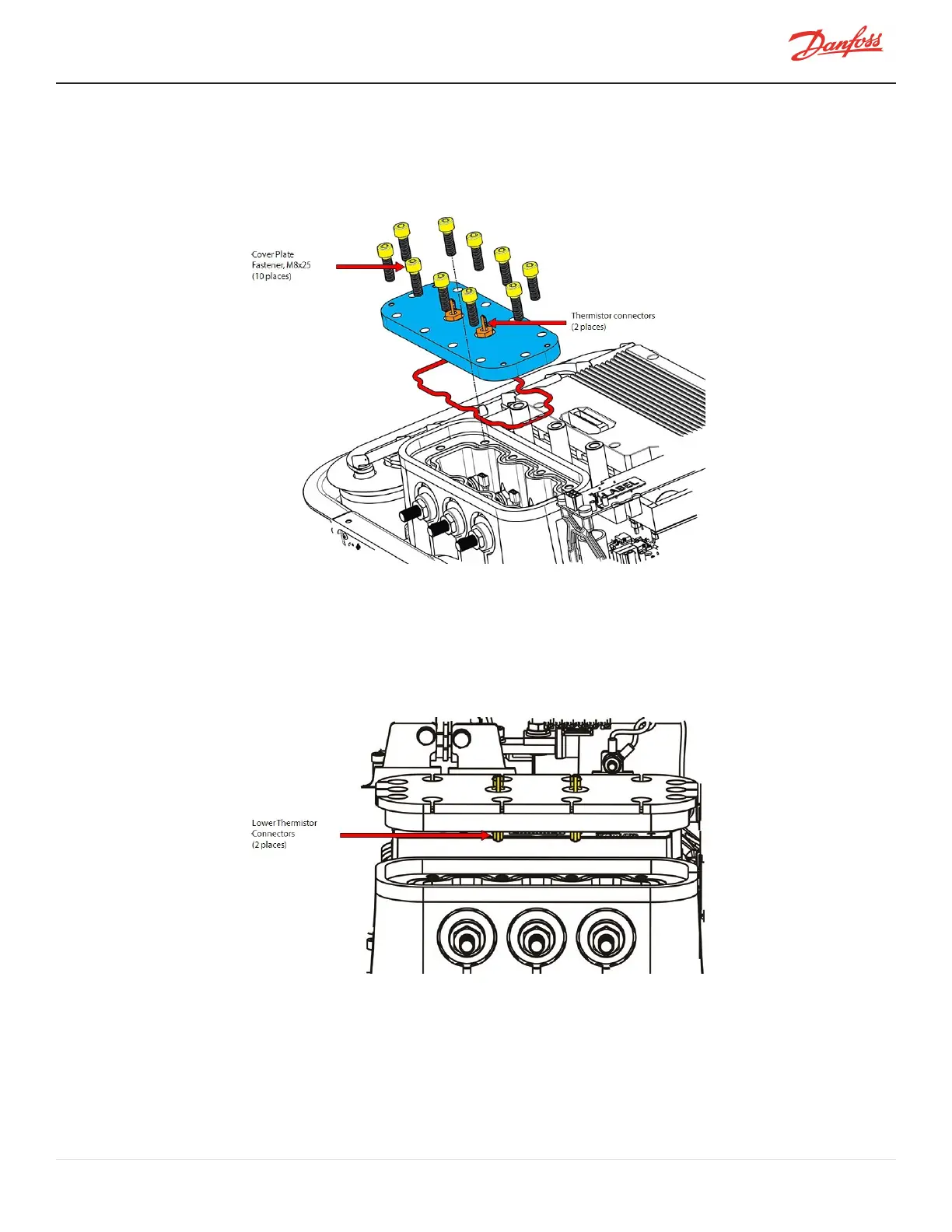
5. Disconnectthetwo(2)connectorsfromthermistorsensorfeedthrough.RefertoFigure4-222Motor
CoverPlateRemoval.
Figure 4-222 Motor Cover Plate Removal
6. Removethe10M8x25fastenersthatsecuretheCoverPlatetotheMainhousing.RefertoFigure4-222
MotorCoverPlateRemoval.
7. Cuttheinsulation(ifnecessary)inordertoremovetheCoverPlate.
8. LifttheCoverPlateslightlytopreventbreakingtheconnectionsandcarefullyunplugthelower
thermistorconnectors.RefertoFigure4-223ThermistorConnectorRemoval.
Figure 4-223 Thermistor Connector Removal
9. RemoveanddiscardtheO-ringfromthecompressorhousing.
4.23.5.6 Motor Cover Plate Installation
1. Cleanthematingsurfaceswithalint-freecloth.Inspectthesealingareaforanydamage.
2. LubricateandinstallthepreformedO-ringintothegroovelocatedintheMainhousing.
M-SV-001-EN Rev. H-1/23/2023 Page 199 of 294