5. DisconnectthePWMconnectorsfromthecompressorhousingbearingfeedthroughs,keepingthe
PWMattachedtotheBackplane.RefertoFigure4-251PWMonpage225.
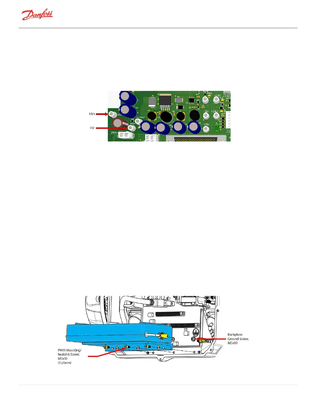
6. Usingamultimetersetfordiodemeasurements,placethered(+)leadontheHV-testpointofthe
Backplaneandtheblack(-)leadinthefirstpinholeofthePWMconnector,ensuretheleadmakes
contactwiththeclipinthepinhole.RefertoFigure4-253ConnectingLeadstoPWMConnectorand
HV-andHV+TestPoints.Themeasuredvoltagedropshouldbe0.39-0.46VDC.
7. RepeatStep6forall10-pinholesonbothleftandrightPWMconnectors.
Figure 4-253 Connecting Leads to PWM Connector and HV- and HV+ Test Points
8. Stillsetondiodemeasurement,placetheblack(-)multimeterleadontheHV+testpointofthe
Backplaneandthered(+)multimeterleadinthefirstpinholeofthePWMconnector,ensurethelead
makescontactwiththeclipinthepinhole.RefertoFigure4-253ConnectingLeadstoPWMConnector
andHV-andHV+TestPoints.Themeasuredvoltagedropshouldbe0.39-0.46VDC.
9. Repeatforall10-pinholesofbothPWMconnectors.
10. Ifanyofthetestresultsareoutofthe0.39-0.46VDCrange,thePWMisdefectiveandshouldbe
replaced.
4.28.4 PWM Removal and Installation
4.28.4.1 PWM Amplifier Removal
1. Isolatecompressorpower.
2. RemovetheServiceSideCover.RefertoSection4.1.3.1ServiceSideCoverRemovalandInstallationon
page54.
3. WaitfortheLEDsontheBackplanetoturnoff.
4. RemovetheSerialDriver.RefertoSection4.26.4SerialDriverRemovalandInstallationonpage218.
5. RemovetheBMCC.RefertoSection4.27BMCConpage220.
6. Disconnectthetwo(2)connectorsforthePWMandbearingpowerfeedthroughs.
7. RemovethefastenersbelowthePWMthatsecuretheheatsinktothemaincompressorhousing.Refer
toFigure4-254RemovingthePWMAmplifier.
Figure 4-254 Removing the PWM Amplifier
Page 228 of 294 - M-SV-001-EN Rev. H 1/23/2023