4.5.2 Compressor Controller Cable Harness Removal and Installation
Compressor Controller Cable Harness Removal
1. IsolatecompressorpowerasdescribedinSection1.8ElectricalIsolationonpage22.
2. RemovetheServiceSideCover.RefertoSection4.1.3.1ServiceSideCoverRemovalandInstallationon
page54.
3. RemovetheSoftStart.RefertoSection4.14.3SoftStartRemovalandInstallationonpage117.
4. RemovetheTerminalBlockAssembly(excludingTTS300/TGS230compressors).RefertoSection4.11.2
3-PhaseMainVoltageInputTerminalBlockRemovalandInstallationonpage102.
5. RemovetheDCBusBarandCapacitorAssembly.RefertoSection4.21.3DCCapacitorBusBarAssembly
RemovalandInstallationonpage168.
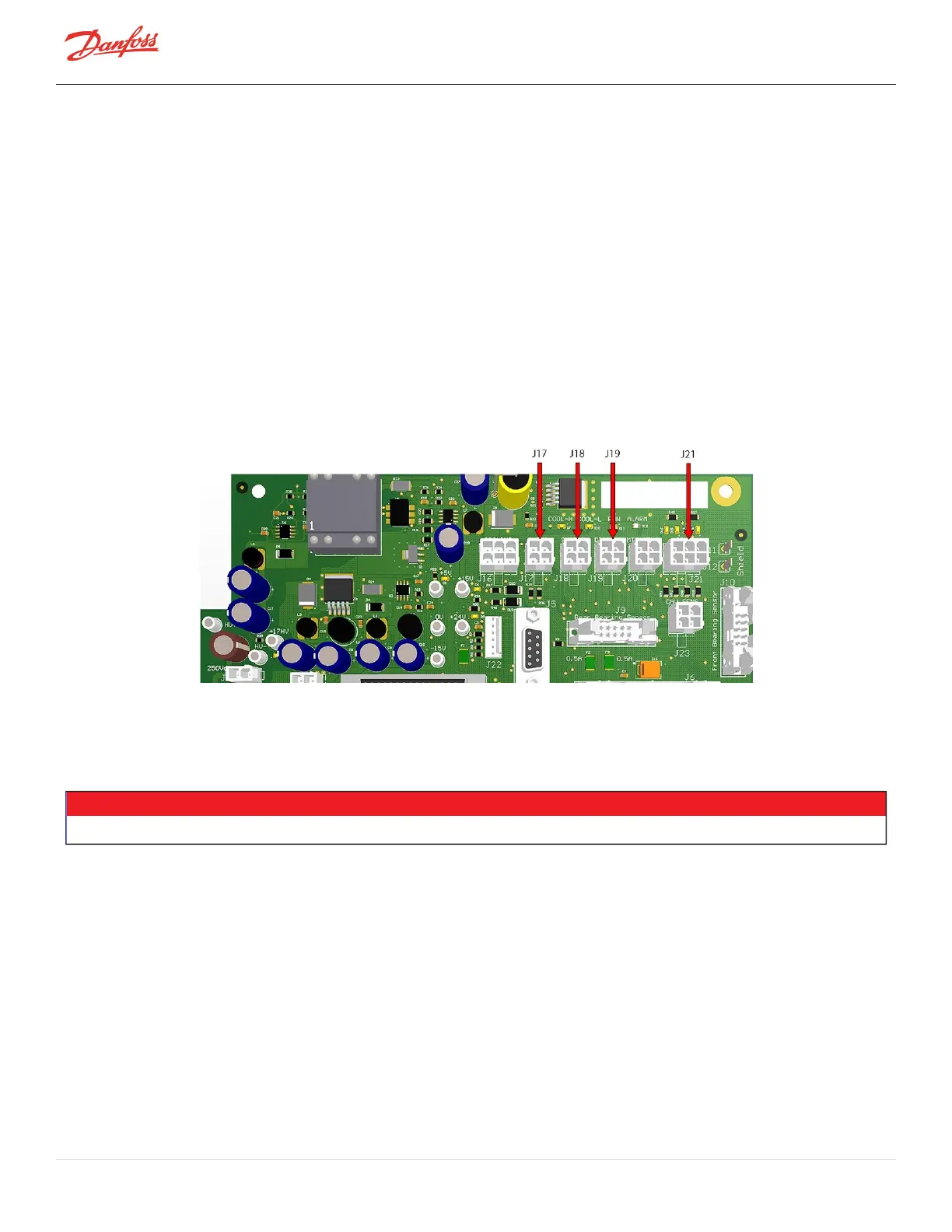
6. RefertoFigure4-22BackplaneConnectionsandremovethefollowingconnectorsfromtheBackplane:
l
Pressure/temperaturesensorconnectors(J17,J18,andJ19)
l
IGVmotordriveconnector(J21)
Figure 4-22 Backplane Connections
7. Disconnectthecablesfromthesuctionanddischargepressuresensors.RefertoFigure4-23
Pressure/TemperatureandSCRTemperatureSensorLocations-TTS300/TGS230onpage69,Figure4-
24Pressure/TempandSCRTempSensorLocations-TTS/TGS(ExceptTTS300/TGS230)onpage69,and
Figure4-25Pressure/TemperatureSensorLocations-TTH375/TGH285onpage69forthisandthe
followingstep.
NOTE
AllTTH/TGHcompressorsandallTTS/TGSMajorRevHandlatercompressorsdonotcontainanSCRTemperatureSensor.
Page 68 of 294 - M-SV-001-EN Rev. H 1/23/2023