4.9.3.2 IGV Assembly Removal
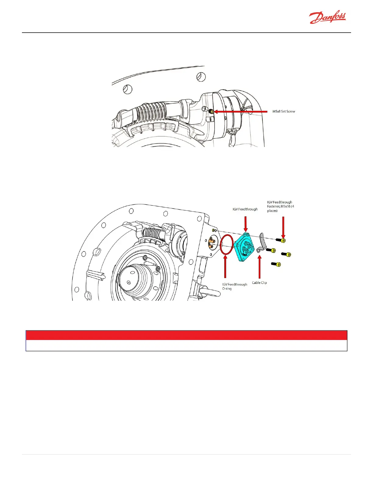
Figure 4-54 Set Screw Removal
1. RemovetheIGVHousingAssembly.
2. Removethefour(4)M5x16fastenersandseparatethefour-pinFeedthroughfromtheIGVHousing.
RefertoFigure4-55IGVFeedthroughRemoval.
Figure 4-55 IGV Feedthrough Removal
3. Disconnectthefour(4)wiresfromthefour-pinFeedthrough.Noteandrecordpositionofwirecolorsto
theircorrespondingpins.Expected:1=Red,2=Gray,3=Yellow,and4=Black.RefertoTable4-15IGV
FeedthroughWiringOrderonpage92.
NOTE
Thecolorsassociatedwitheachpincouldvary,sobesuretoidentifythoseontherespectivecompressor.
4. RemovetheIGVMotorassemblybypullingawayfromwormshaft.RefertoFigure4-56IGVMotor
AssemblyRemovalonpage88.SupportthebottomoftheIGVMotortopreventdamagetothemotor
shaft.Alighttaponthemotorlocatingscrewwithatoolmayhelpreleasethemotorshaftfromthe
wormgear.
5. Ifnecessary,usingaStepperMotorDriver,turnthewormgearandVaneDriveassemblytopositionthe
motorshaftsothatlockingsetscrewisalignedwiththeholeshowninFigure4-54SetScrewRemoval.
Useneedle-nosepliersorsimilartooltoturnthewormgearifaStepperMotorDriverisnotavailable.
6. Removethesetscrewcompletelyusinga2.5mmhexbittoreleasethemotorfromthewormgear.
M-SV-001-EN Rev. H-1/23/2023 Page 87 of 294