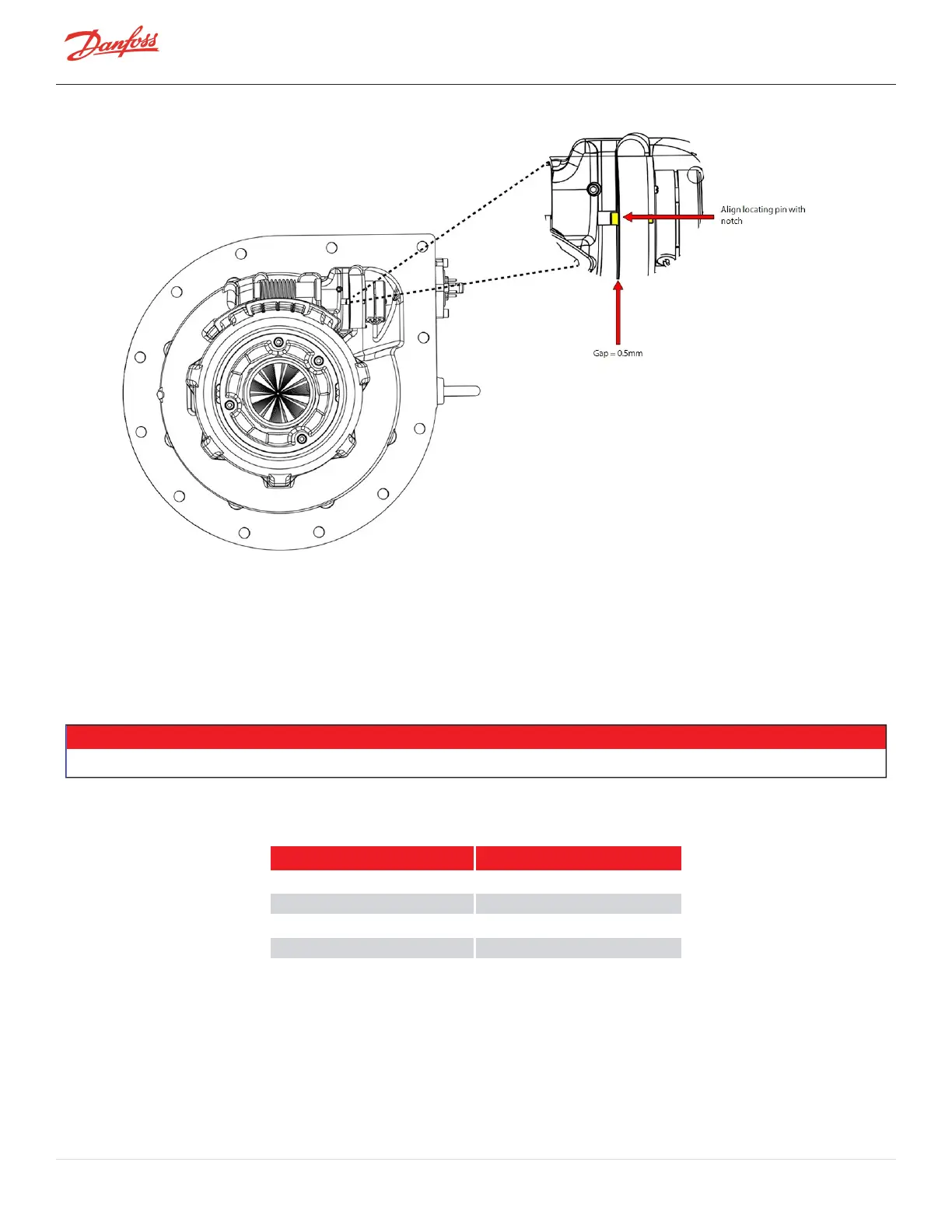
Figure 4-66 IGV Motor Alignment
16. Putone(1)dropofthreadlocker(Loctite243blueorequivalent)onthethreadsofthesmallsetscrew.
Whilepushingin,onthebacksideofthemotor,securethewormgearsetscrewtotheflatsurfaceof
themotorshaftusinga2.5mmhexbit.Rockthemotorbackwardsandforwardswhiletighteningto
ensurefullandcorrectengagementofthescrewtotheflatofthemotorshaft.Torquethesetscrewto
5Nm(44in.lb.).RefertoFigure4-64IGVWormGearAlignmentonpage91.
17. Clean,lubricate,andinstalltheO-ringontheFeedthroughbeforeconnectingthewires.
18. InsertthemotorwiresontotheFeedthroughpinsinaccordancewithTable4-15IGVFeedthrough
WiringOrder.Alsoreferenceyournotesfromremoval.
NOTE
Thecolorsassociatedwitheachpincouldvary,sobesuretorefertonotestakenduringremoval.
Table 4-15 IGV Feedthrough Wiring Order
Color Pin #
Red 1
Gray 2
Yellow 3
Black 4
Page 92 of 294 - M-SV-001-EN Rev. H 1/23/2023