13. InspecttheIGVHousingassemblyforresidue/contaminationorforeignobjects.
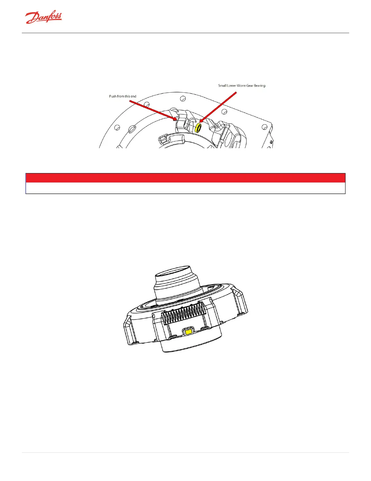
14. Removethesmalllowerwormgearbearingfromthehousing.Performthisstepbypushingthe
bearingoutfromtheportbelowthebearing.RefertoFigure4-62SmallWormGearBearing.
Figure 4-62 Small Worm Gear Bearing
4.9.3.3 IGV Assembly Installation
• • • CAUTION • • •
FittingincorrectIGVcomponentsforthespecificcompressormodelwillresultinphysicaldamagetothecompressor.
1. Ensurethatallcomponentsandthreadsareclear,clean,andoilfree.
2. Installthelower(small)wormgearbearingintothehousing.Thismayrequireaverylighttapwitha
hammer.Ensurethelowerwormgearbearingisfullyseatedintothehousing.RefertoFigure4-62
SmallWormGearBearing.
3. EnsuretheIGVpositionindicatormagnetisinplaceintheIGVThroatassembly.RefertoFigure4-63
IGVPositionIndicatorMagnet.
Figure 4-63 IGV Position Indicator Magnet
4. PlacetheIGVThroatassemblyintotheIGVHousingorientatingtheIGVThroatthreadsdirectlybelow
theIGVMotorMount.
5. Addone(1)dropofthreadlocker(Loctite243blueorequivalent)totheIGVThroatfastenerthreads
andinstall.Torqueto5Nm(44in.lb.).
6. Rotatetheouterringofthedriveassemblyandensurethattheguidevanesmovefreely.Theassembly
mustrotateoveraspanwherethevanesareopen(perpendiculartogasflow)andfullyclosed.
7. Fittheupper(large)bearingtothewormgearandinstallthesnapring.RefertoFigure4-60Large
WormGearBearingonpage89.
Page 90 of 294 - M-SV-001-EN Rev. H 1/23/2023