8. Installthewormgearintothehousingby“screwing”thewormgearalongtheIGVThroatGear.Locate
thewormgearshaftintothebottom(small)bearing.
9. PlacethethreadedLockingCollaronthefour(4)pinsoftheCollartoolandinstallintothehousing.
NOTE
Ensuretheflatsideofthecollarisagainstthetool.
10. TurntheLockingCollarcounterclockwiseandtorqueto5Nm(44in.lb.).RefertoFigure4-58Locking
Collaronpage88.
NOTE
Lockingcollarisaleft-handthread.Turncounter-clockwisewhenviewedfrommotorendtotighten(donotusethreadlockeroncollar).
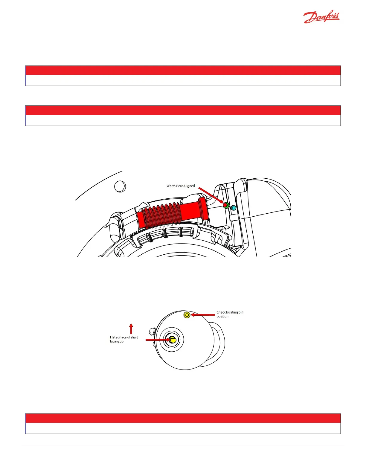
11. Rotatethewormgearbyhanduntilthesetscrewholeinthewormgearisvisiblethroughtheaccess
holeinthecasting.Verifythatthewormgearturnsfreely.Donotinstallthesetscrewatthistime.
RefertoFigure4-64IGVWormGearAlignment.
Figure 4-64 IGV Worm Gear Alignment
12. InserttheIGVMotorwiresthroughtheFeedthroughhole.
13. Checkthepositionoftheflatsurfaceoftheshaftrelativetothelocatingpin.Theflatsurfaceshouldbe
orientedfacingup,readytoreceivethesetscrew;adjustifnecessary.RefertoFigure4-65Shaft
Position.
Figure 4-65 Shaft Position
14. Installthemotorintothehousingandalignthemotorshaftflatsurfacewithwormgearshaft.
15. Ensurethemotorlocatingpinisalignedwiththenotchinthehousingflange.RefertoFigure4-66IGV
MotorAlignmentonpage92.
• • • CAUTION • • •
Checkthatwiringisclearofhousingandedgesofmotor.
M-SV-001-EN Rev. H-1/23/2023 Page 91 of 294