4.22 Inverter
ThefunctionoftheInverteristotaketheDCbusvoltageasaninputandgeneratetheACoutputvoltagetothe
compressormotorattherequiredfundamentalfrequencytogeneratetherequestedshaftspeed.Voltagetothe
motorisalsocontrolledtoprovidetheappropriatemotortorque.
TheBackplanesends+24VDCandgatingsignalstotheInverterfromtheBMCC.Inreturn,theInvertersendscurrent,
temperature,error,andDCbusvoltageinformationtotheBMCCviatheBackplane.Motorcurrentsandvoltages
displayedintheSMTcannotbedirectlycomparedorcorrelatedtoincoming3-phaseACvalues.
Intheeventofa3-phasevoltagepowerlosswhilethecompressorisrunning,theInverterswitchestoGenerator
Mode,actingasarectifiertomaintaintheDCbusvoltageuntiltheshaftcomestoacompletestopandde-levitates.
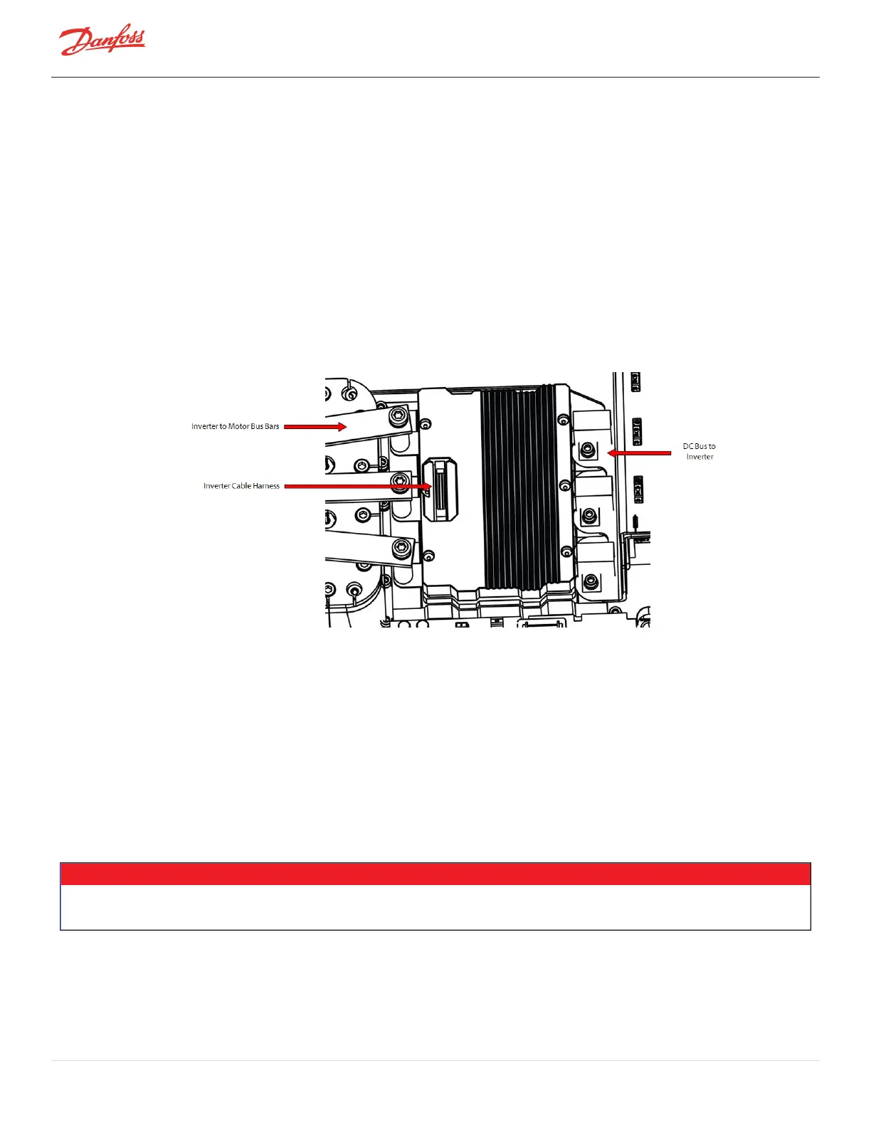
4.22.1 Inverter Connections
Figure 4-189 Inverter Connections
4.22.2 Inverter Verification
ThisprocedureonlyverifiestheInverterhigh-powerdiodes.TheInverterControlBoardcannotbeverifiedinthe
fieldunlessaninvertertesterisused.AfaultyInvertermayalsoappearasan“InverterError”fault.
1. IsolatethecompressorpowerasdescribedinSection1.8ElectricalIsolationonpage22.
2. RemovetheSoftStartModule.RefertoSection4.14.3SoftStartRemovalandInstallationonpage117.
3. RemovetheDCCapacitorBusBarAssembly.RefertoSection4.21.3DCCapacitorBusBarAssembly
RemovalandInstallationonpage168.
4. RemovetheCopperTubesandfastenersconnectingthemotorbusbarstotheInverterModule.Refer
toFigure4-195InverterCopperTubeRemovalonpage180.
5. DisconnecttheInverterribboncablefromtheInverterModule.
• • • CAUTION • • •
AfaultyInvertermodulecouldbetheresultofafaultyStator.IfanInvertermoduleisfoundtobefaulty,theStatormustbeverifiedas
well.
6. Usingamultimetersetfordiodemeasurements,placethered(+)multimeterleadonthephase1AC
terminalandtheblack(-)multimeterleadontheDC+terminal.Themeasuredvalueshouldbe0.275V–
0.4V.RefertoFigure4-190InverterDiodeMeasurements(Skiip613Shown)onpage177forthisand
Page 176 of 294 - M-SV-001-EN Rev. H 1/23/2023