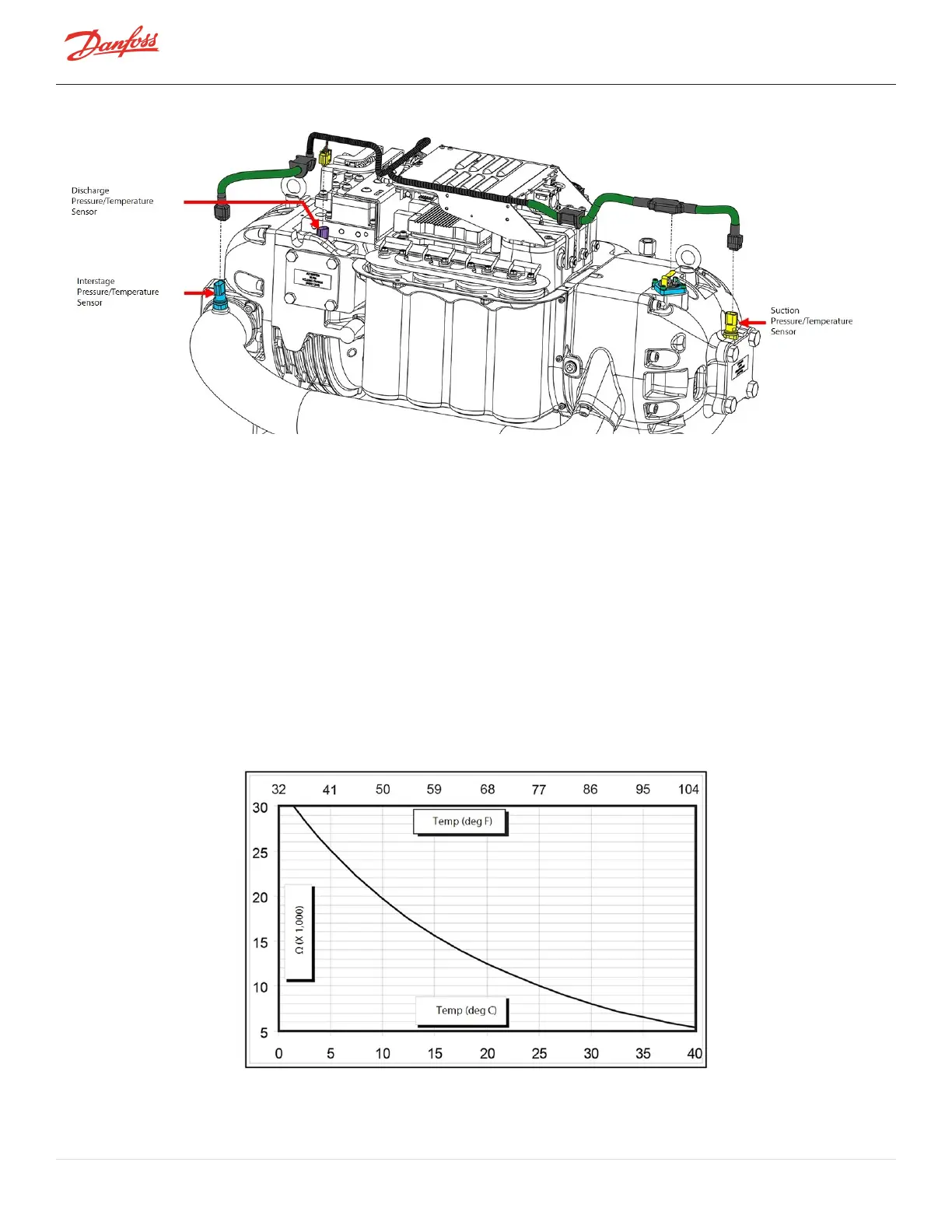
Figure 4-272 Pressure/Temperature Sensor Locations (TTH/TGH)
ThesensorconnectorclipslinktothecompressorcontrolcablewhichthenconnecttotheBackplaneatJ18andJ19
(andJ17forTTH/TGHonly).
4.32.3 Pressure/Temperature Sensor Verification
1. IsolatethecompressorpowerasdescribedinSection1.8ElectricalIsolationonpage22.
2. RemovetheServiceSideCover.RefertoSection4.1.3.1ServiceSideCoverRemovalandInstallationon
page54.
3. Disconnectthepressure/temperaturecableclip(SUCTION–J18orDISCHGE–J19orINTER-J17)from
theBackplaneboard.RefertoFigure4-274Pressure/TemperatureCableTerminalsonpage247forthis
andthefollowingstep.
4. Usingamultimetersetforresistancemeasurements,placeleadsonTerminal1andTerminal2ofthe
pressure/temperaturecableclip.
l
Thetemperaturesensorisa10KΩ@77°F(25°C)NTCthermistor.Theresistancevalueshould
correspondtoFigure4-273Temperaturevs.Resistance.
Figure 4-273 Temperature vs. Resistance
Page 246 of 294 - M-SV-001-EN Rev. H 1/23/2023