128 of 132
M-SV-001-EN Rev.E
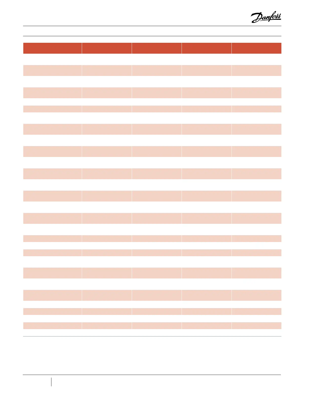
Component Test Point Expected Value
Verification
Section
Measured Value
Phase 2: - Lead on AC
Output to - DC input
0.275V – 0.4V 3.7.3
Phase 2: - Lead on AC
Output to + DC input
Open 3.7.3
Phase 3: - Lead on AC
Output to - DC input
0.275V – 0.4V 3.7.3
Phase 3: - Lead on AC
Output to + DC input
Open 3.7.3
IGV Motor Resistance 1 to 2 46Ω to 59Ω 3.13.3
3 to 4 46Ω to 59Ω 3.13.3
Interlock
Power On: I/Lock - to
Ground
0VDC 3.15.3.3
Power On: J2 Removed
I/Lock - to I/Lock +
2.2 to 3.7 VDC 3.15.3.3
Power Off: J2 Removed
I/Lock - to I/Lock +
< 22 kΩ 3.15.3.3
Pressure/Temperature Sensor
Resistance
1 to 3
(1 to 2 of the plug)
10KΩ @ 77°F (25°C) 3.20.3
PWM Diode
Lead in HV-; - lead in PWM
connector
0.39-0.46VDC 3.16.3.3
- Lead in HV+; +C47 lead in
PWM connector
0.39-0.46VDC 3.16.3.3
Rear Bearing Feed Through
Resistance
All models
1 to 6
2.7 to 3.25Ω 3.17.3
All models
2 to 5
2.7 to 3.25Ω 3.17.3
TT300/TG230
3 to 4
5.7 to 6.2Ω 3.17.3
All models except TT300:
3 to 4
6.0 to 6.7Ω 3.17.3
Rear Bearing Sesor Feed Through
Resistance
5 to 2 2.0Ω to 3.5Ω 3.18.3
5 to 3 2.0Ω to 3.5Ω 3.18.3
6 to 7 2.0Ω to 3.5Ω 3.18.3
6 to 8 2.0Ω to 3.5Ω 3.18.3
SCR Diode
positive (+) on 1 negative
(-) on 2
∞ or open 3.5.3
positive (+) on 1 negative
(-) on 3
∞ or open 3.5.3
positive (+) on 2 negative
(-) on 1
∞ or open 3.5.3
positive (+) on 3 negative
(-) on 1
0.3V to 0.45V 3.5.3
SCR Gate Resistance Gate Terminals >1Ω and <25Ω (all models) 3.5.3.2
SCR Temperature Sensor J17 Sensor connector 10KΩ @ 70°F (21°C) 3.5.3.3
Soft Start Fuses F1 around 0.25Ω 3.4.3.2
F2 around 1Ω 3.4.3.2
F3 around 0.5Ω 3.4.3.2
Appendix C Compressor Test Sheet

 Loading...


