29-04 Pipe Fill Rate
Range: Function:
0.001
ProcessCtrlUnit*
[0.001 -
999999.999
ProcessCtrlUnit]
Species the ll rate in units
using the PI controller. Fill
rate units are feedback units.
This function is used for
lling up vertical pipe
systems, but is active when
the lling time has expired,
until the pipe ll setpoint set
in parameter 29-05 Filled
Setpoint is reached.
29-05 Filled Setpoint
Range: Function:
0
ProcessCtrlUnit*
[-999999.999 -
999999.999
ProcessCtrlUnit]
Species the lled
setpoint at which the pipe
ll function is disabled
and the PID controller
takes control. This
function can be used both
for horizontal and vertical
pipe systems.
29-06 No-Flow Disable Timer
Range: Function:
0 s* [0 - 3600 s]
29-07 Filled setpoint delay
Range: Function:
0 s* [0 - 10 s] Select the delay before the frequency converter
considers the lled setpoint to be reached if a
ll rate in units per second is used.
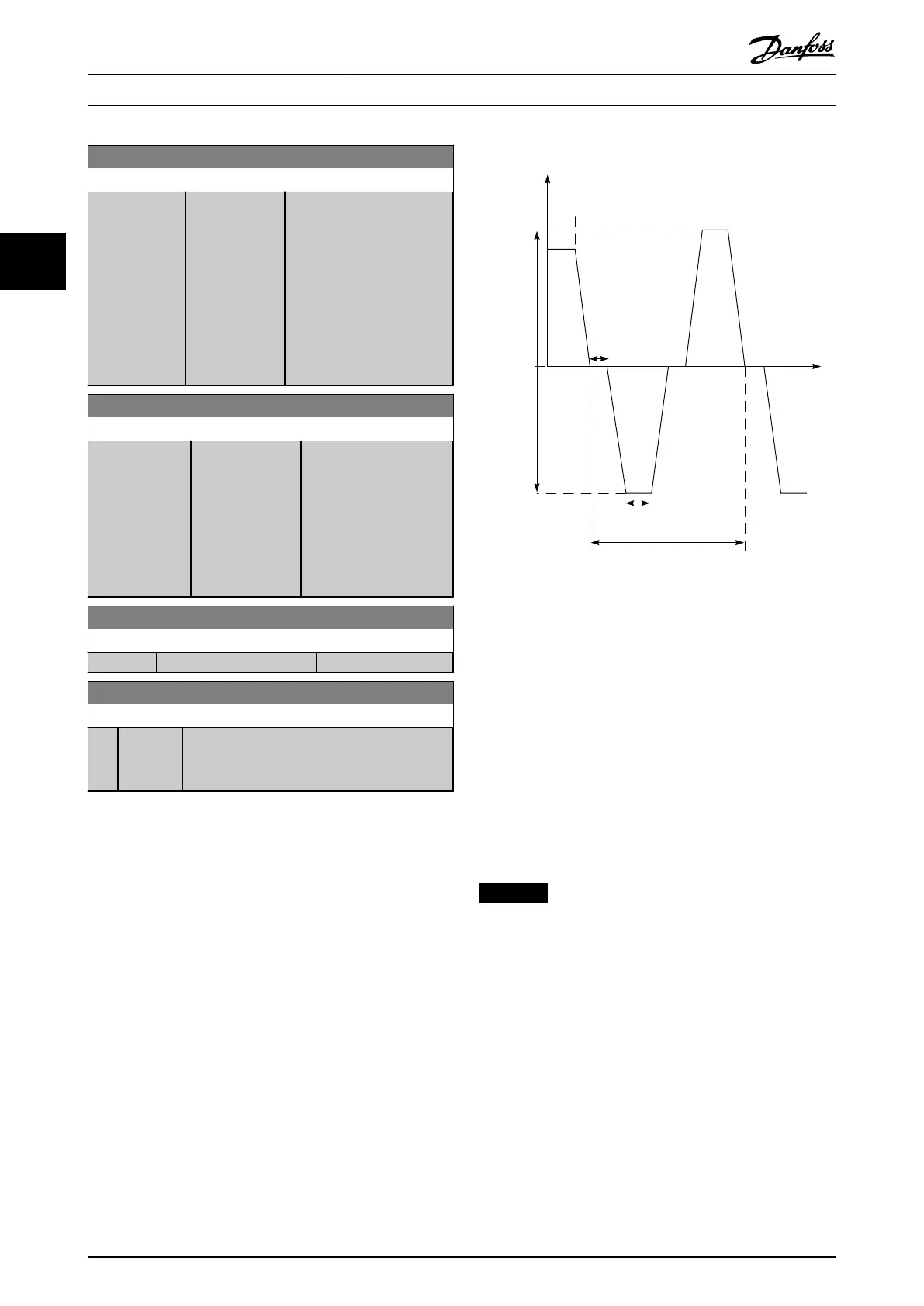
3.25.2 29-1* Deragging Function
The purpose of the deragging feature is to free the pump
blade of debris in waste water applications so that the
pump operates normally.
A deragging event is dened as the time when the
frequency converter starts to derag to when the deragging
nishes. When a derag is started, the frequency converter
ramps rst to a stop and then an o delay expires before
the rst cycle begins.
0 Hz/RPM
Derag off delay:
Par. 29 -15
+/- Derag
speed:
Par.: 29 -13
Par.: 29 -14
Deragging run-time : Par . 29-12
Speed
Derag
function
activated
1 Cycle
Number of cycles : Par . 29 -10
e30bc369.11
Illustration 3.112 Derag Function
If a derag is triggered from a frequency converter-stopped
state, the rst o delay is skipped. The deragging event
may consist of several cycles: one cycle consisting of 1
pulse in the reverse direction followed by 1 pulse in the
forward direction. Deragging is considered nished after
the specied number of cycles have completed. More
specically, on the last pulse (it is always forward) of the
last cycle, the derag is considered nished after the
deragging run-time expires (the frequency converter is
running at derag speed). In between pulses, the frequency
converter output coasts for a specied o-delay time to let
debris in the pump settle.
NOTICE
Do not enable deragging if the pump cannot operate in
reverse direction.
There are 3 dierent notications for an ongoing
deragging event:
•
Status in the LCP: Auto Remote Derag.
•
A bit in the extended status word (bit 23, 80 0000
hex).
•
A digital output can be congured to reect the
active deragging status.
Depending on the application and the purpose of using it,
this feature can be used as a preventive or reactive
measure and can be triggered/started in the following
ways:
Parameter Description
VLT
®
AQUA Drive FC 202
236 Danfoss A/S © 05/2018 All rights reserved. MG20OB02
33

 Loading...


