•
O delay timer=10 s. The nominal power must be
below 10% for 10 s to disconnect the capacitors.
If the nominal power exceeds 10% during the 10
s delay, the timer (10 s) restarts.
•
The capacitor reconnect delay (default=25 s with
a range 1–120 s, see parameter 5-80 AHF Cap
Reconnect Delay) is used for the minimum o-
time for the AHF capacitor output function.
•
If there is a power loss, the frequency converter
guarantees that the minimum o-time is
respected when power is restored.
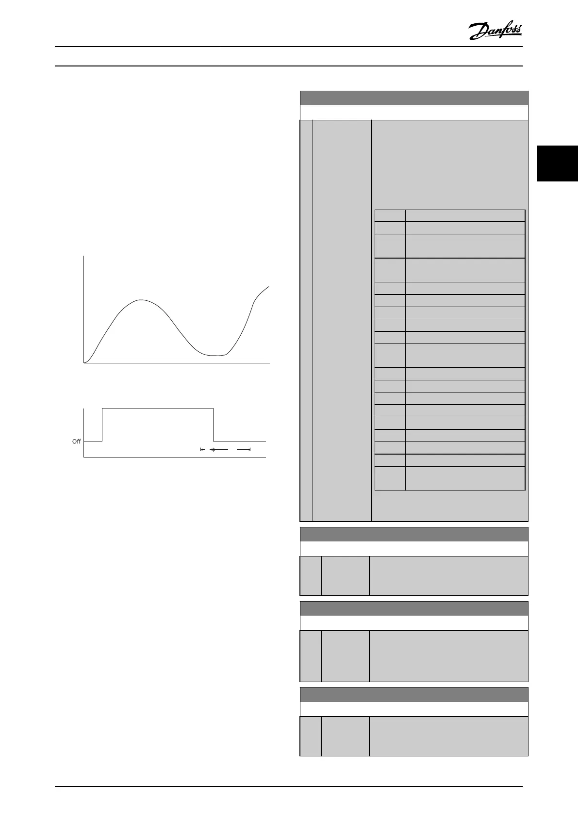
10 20 30 40 50 60 70 80 90 100 110 120 130
Time (s)
Relay Output
On
t
1
t
2
130BC368.10
Nominal Power of Drive
0%
10%
20%
30%
40%
50%
60%
70%
80%
90%
100%
...................................................................................................................................................................................................................
....................................................................................................................................................................................................................
....................................................................................................................................................................................................................
Illustration 3.33 Example of the Output Function
t
1
shows the o delay timer (10 s).
t
2
shows the capacitor reconnect delay (parameter 5-80 AHF
Cap Reconnect Delay).
When the nominal power of the frequency converter
exceeds 20%, the output function turns on. When the
power goes below 10%, an o delay timer has to expire
before the output goes low. This is represented by t
1
. After
the output goes low, the capacitor reconnect delay timer
has to expire before the output is allowed to be on again,
shown by t
2
. When t
2
expires, the nominal power is above
30% and the relay does not turn on.
3.7.7 5-9* Bus-controlled
This parameter group selects digital and relay outputs via a
eldbus setting.
5-90 Digital & Relay Bus Control
Range: Function:
0* [0 -
2147483647 ]
This parameter holds the state of the digital
outputs and relays that are controlled by
bus.
A logical 1 indicates that the output is high
or active.
A logical 0 indicates that the output is low
or inactive.
Bit 0 CC digital output, terminal 27
Bit 1 CC digital output, terminal 29
Bit 2 GPIO digital output, terminal X
30/6
Bit 3 GPIO digital output, terminal X
30/7
Bit 4 CC relay 1 output terminal
Bit 5 CC relay 2 output terminal
Bit 6 Option B relay 1 output terminal
Bit 7 Option B relay 2 output terminal
Bit 8 Option B relay 3 output terminal
Bit 9–
15
Reserved for future terminals
Bit 16 Option C relay 1 output terminal
Bit 17 Option C relay 2 output terminal
Bit 18 Option C relay 3 output terminal
Bit 19 Option C relay 4 output terminal
Bit 20 Option C relay 5 output terminal
Bit 21 Option C relay 6 output terminal
Bit 22 Option C relay 7 output terminal
Bit 23 Option C relay 8 output terminal
Bit 24–
31
Reserved for future terminals
Table 3.16 Digital Output Bits
5-93 Pulse Out #27 Bus Control
Range: Function:
0 %* [0 - 100 %] Contains the frequency to apply to the
digital output terminal 27 when it is
congured as bus-controlled.
5-94 Pulse Out #27 Timeout Preset
Range: Function:
0 %* [0 - 100 %] Contains the frequency to apply to the
digital output terminal 27 when it is
congured as bus-controlled timeout, and
timeout is detected.
5-95 Pulse Out #29 Bus Control
Range: Function:
0 %* [0 - 100 %] Contains the frequency to apply to the
digital output terminal 29 when it is
congured as bus-controlled.
Parameter Description Programming Guide
MG20OB02 Danfoss A/S © 05/2018 All rights reserved. 89
3 3

 Loading...


