The dimensions are only for the physical units, but when
installing in an application it is necessary to add space for
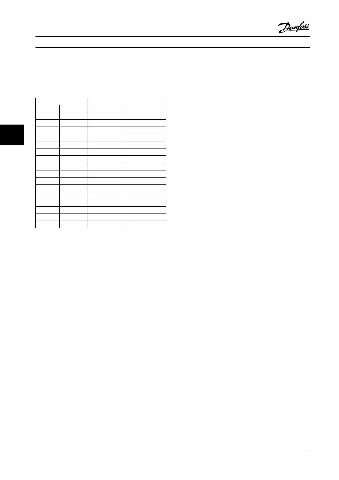
free air passage both above and below the units. The
amount of space for free air passage is listed in Table 5.2:
Enclosure Clearance [mm]
Frame IP class Above unit Below unit
H1 20 100 100
H2 20 100 100
H3 20 100 100
H4 20 100 100
H5 20 100 100
H6 20 200 200
H7 20 200 200
H8 20 225 225
H9 20 100 100
H10 20 200 200
I2 54 100 100
I3 54 100 100
I4 54 100 100
I6 54 200 200
I7 54 200 200
I8 54 225 225
Table 5.2 Clearance Needed for Free Air Passage
How to Install Design Guide
56 Danfoss A/S © Rev. 2014-01-14 All rights reserved. MG18C522
55

 Loading...


