+DC
BR-
BR+
U
V
W
MAINS
L1 L2 L3
91 92 93
RELAY 1 RELAY 2
99
- LC -
130BA264.10
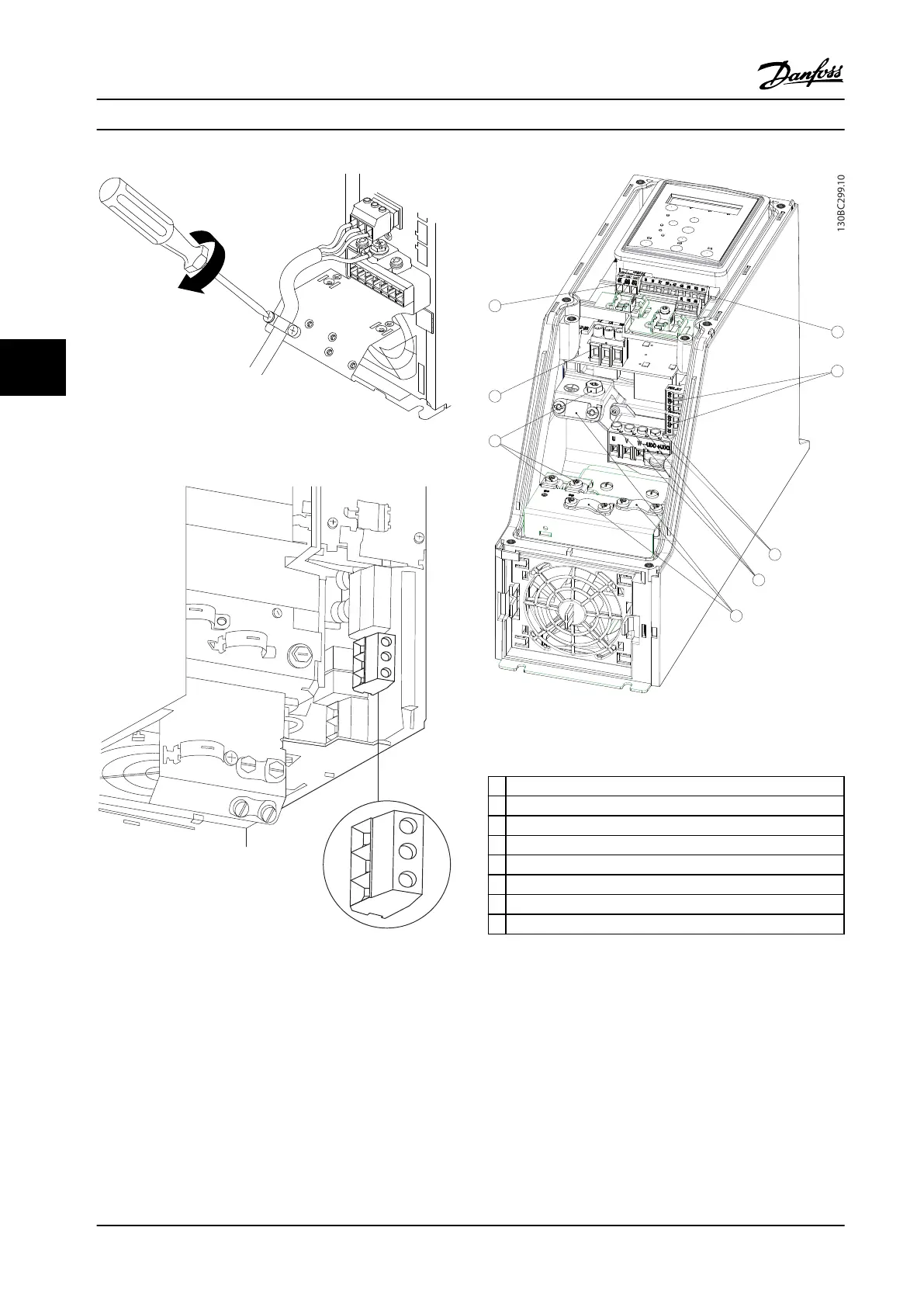
Figure 5.10 Tighten support bracket on line power wires.
Figure 5.11 H10 Frame
IP20 600 V 15–20 hp [11–15 kW]
Figure 5.12 I2 Frame
IP54 380–480 V 1–5 hp [0.75–4.0 kW]
1
RS-485
2 Line in
3 Ground
4 Wire clamps
5 Motor
6 UDC
7 Relays
8 I/O
Table 5.11 Legend to Figure 5.12
How to Install Design Guide
64 Danfoss A/S © Rev. 2014-01-14 All rights reserved. MG18C522
55

 Loading...


