53
I-Class Mark II Maintenance Manual
Removal and Replacement
Replacement:
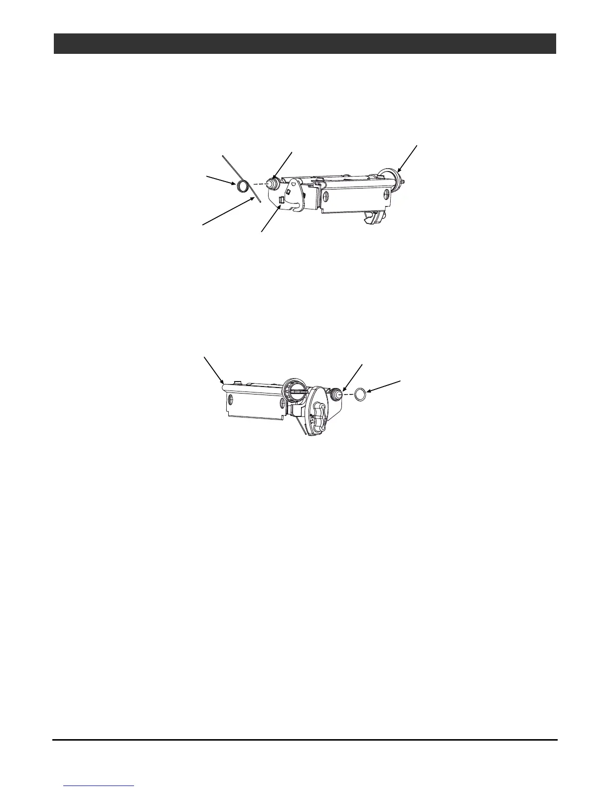
1. Place the Head Lift Spring onto the Printhead Assembly Boss; situate the Short Leg behind the Tab.
Head
Lift Spring
Tab
Boss
Printhead
Assembly
Short Leg
2. Rotate the Long Leg of the Head Lift Spring downward, loading it against the Extrusion, and then insert
the Printhead Boss into the Centerplate bushing.
3. While holding the spring-loaded Printhead Assembly in the Centerplate bushing, place the Wavy Washer
onto the (opposite) Printhead Assembly Boss.
Printhead
Assembly
Boss
Wavy
Washer
4. If removed, insert the Ribbon Idler shaft into the Centerplate bushing.
5. With the bushings installed in the End Cap, reinstall the End Cap onto the Extrusion to captivate the
Printhead Assembly Boss and Ribbon Idler shaft. Then secure the End Cap with the two Screws.
6. Test the Printhead Assembly for correct movement and latching; also, check the Ribbon Idler for proper
rotation.
7. Reinstall the Printhead; see Section 4.4.

 Loading...


