EasyManuals Logo

Datamax I-Class Mark II Maintenance Manual

Datamax I-Class Mark II
74 pages
To Next Page IconTo Next Page
To Previous Page IconTo Previous Page
Page #62 background imageLoading...
Page #62 background image
58
I-Class Mark II Maintenance Manual
Removal and Replacement
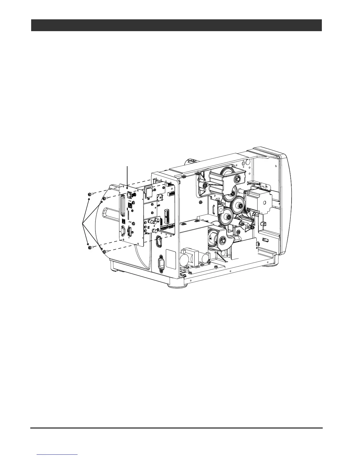
4.9 Main Logic PCB
Removal:
1. Turn OFF and unplug the printer. Remove the Cover Assembly (see Section 4.1).
2. Disconnect the interface cable(s) from the Main Logic PCB.
3. Remove the four Screws on the rear of the printer that secure the Main Logic PCB.
4. Slide out the Main Logic PCB from the printer.
Screws
Main Logic PCB
Replacement:
1. If necessary transfer any option cards to the new replacement Main Logic PCB.
2. Insert the Main Logic PCB into the printer then slide it forward until seated.
3. Reinstall the four previously removed screws that secure the Main Logic PCB.
4. Reinstall the cable(s).
5. Verify the installed Firmware Version for the printer and update if necessary; see Section 2.5.
6. Perform a media calibration; see Section 2.1

Other manuals for Datamax I-Class Mark II

Questions and Answers:

Question and Answer IconNeed help?

Do you have a question about the Datamax I-Class Mark II and is the answer not in the manual?

Datamax I-Class Mark II Specifications

General IconGeneral
Power Supply100-240 VAC, 50-60 Hz
Print Resolution203 dpi
Print Width4.09 inches
Memory16 MB DRAM, 8 MB Flash
ConnectivityUSB, Serial, Ethernet
Media HandlingRoll-fed
Media Width1.0" – 4.65" (25.4 mm – 118 mm)
Media Thickness0.0025" – 0.010" (0.0635 mm – 0.254 mm)
Ribbon Width1.0" – 4.5" (25.4 mm – 114.3 mm)
Ribbon Length1968 feet (600 meters)
Print Speedup to 12 ips
Dimensions12.7" H x 12.6" W x 18.6" D (322.6 mm H x 320 mm W x 472.4 mm D)

Related product manuals