EasyManuals Logo

Datamax I-Class Mark II Maintenance Manual

Datamax I-Class Mark II
74 pages
To Next Page IconTo Next Page
To Previous Page IconTo Previous Page
Page #64 background imageLoading...
Page #64 background image
60
I-Class Mark II Maintenance Manual
Removal and Replacement
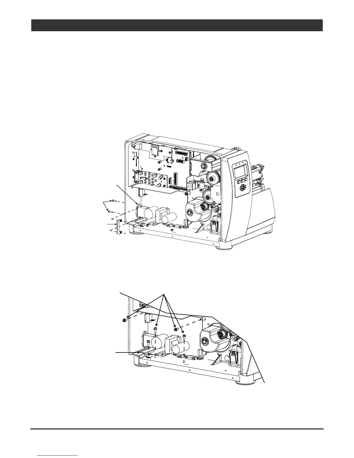
4.11 Power Supply PCB
Removal:
1. Turn OFF and unplug the printer.
2. Remove the Cover Assembly; see Section 4.1.
3. Disconnect the cables from the Power Supply PCB.
4. Remove the two Screws and Nut Plate that secure the AC Connector.
AC Connector
Screws
Nut Plate
5. Remove the Screw and Washer that secures the Ground Wire Lug to the chassis.
6. Remove the four Screws that secure the Power Supply PCB and then remove the Power Supply PCB.
Screws
Ground
Wire Lug

Other manuals for Datamax I-Class Mark II

Questions and Answers:

Question and Answer IconNeed help?

Do you have a question about the Datamax I-Class Mark II and is the answer not in the manual?

Datamax I-Class Mark II Specifications

General IconGeneral
Power Supply100-240 VAC, 50-60 Hz
Print Resolution203 dpi
Print Width4.09 inches
Memory16 MB DRAM, 8 MB Flash
ConnectivityUSB, Serial, Ethernet
Media HandlingRoll-fed
Media Width1.0" – 4.65" (25.4 mm – 118 mm)
Media Thickness0.0025" – 0.010" (0.0635 mm – 0.254 mm)
Ribbon Width1.0" – 4.5" (25.4 mm – 114.3 mm)
Ribbon Length1968 feet (600 meters)
Print Speedup to 12 ips
Dimensions12.7" H x 12.6" W x 18.6" D (322.6 mm H x 320 mm W x 472.4 mm D)

Related product manuals