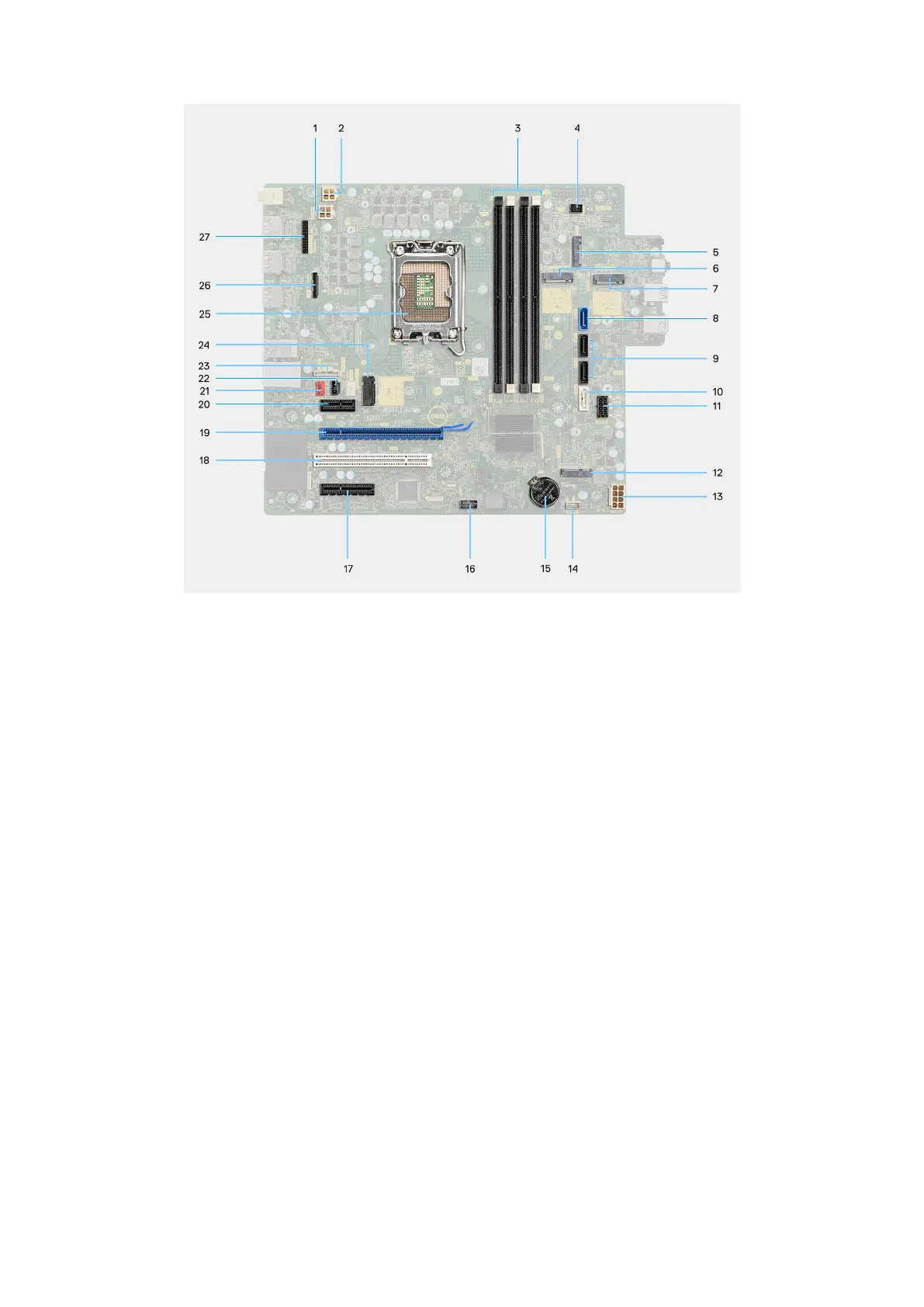
Figure 96. System board connectors
1. Power-supply unit cable connector (ATX CPU1)
2. Power-supply unit cable connector (ATX CPU2)
3. Memory module connectors (DIMM3, DIMM1, DIMM4, DIMM2)
4. Power-button cable connector (PWR SW)
5. Media-card reader connector (SD CARD)
6. M.2 2230/2280 solid-state drive connector (M.2 PCIe SSD-1)
7. M.2 2230 solid-state drive connector (M.2 PCIe SSD-2)
8. Hard-drive data cable connector (SATA0)
9. Hard drive/Slim optical drive power cable connector (SATA1 and SATA2)
10. Slim optical drive data cable connector (SATA3)
11. SATA power cable connector (SATA PWR)
12. Wireless card connector (M.2 WLAN)
13. Power-supply unit cable connector (ATX SYS)
14. Internal-speaker cable connector (INT SPKR)
15. Coin-cell battery connector (RTC)
16. Thunderbolt card connector (TBT)
17. PCIe x4 card connector (SLOT4)
18. PCI card connector (SLOT3)
19. PCIe x16 card connector (SLOT2)
20. PCIe x1 card connector (SLOT1)
21. System-fan cable connector (FAN SYS)
22. Intrusion-switch cable connector (INTRUSION)
23. USB Type-C port connector (TYPE-C)
24. M.2 2230/2280 solid-state drive connector (M.2 PCIe SSD-0)
25. Processor socket (CPU)
26. Optional video port connector (VIDEO)
27. Optional serial port connector (KB MS SERIAL)
The following images indicate the location of the system board and provide a visual representation of the removal procedure.
126
Removing and installing Field Replaceable Units (FRUs)