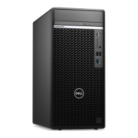
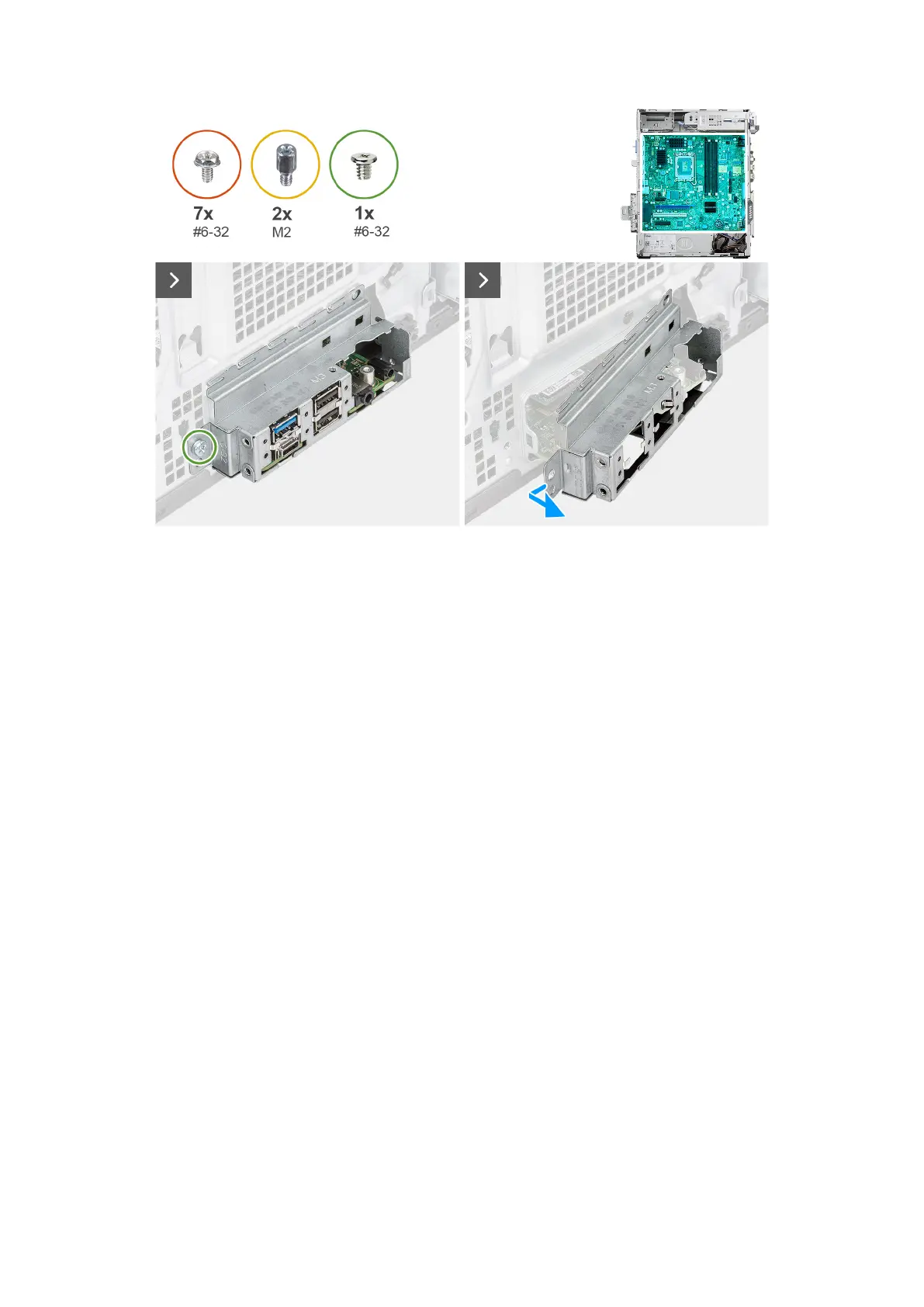
Figure 97. Removing the system board
Steps
1. Remove the screw (#6-32) that secures the front I/O-bracket to the chassis.
2. Slide and remove the front I/O-bracket from the chassis.
3. Disconnect the following cables from the respective connectors on the system board and remove them from the retention
clips on the chassis, if applicable:
a. Power-supply unit cables (ATX CPU1, ATX CPU2 and ATX SYS)
b. Slim optical drive cable (SATA3)
c. Hard drive cables (SATA0 and SATA PWR)
d. Internal-speaker cable (INT SPKR)
e. Intrusion-switch cable (INTRUSION)
Removing and installing Field Replaceable Units (FRUs)
127