Chapter 7 Servo Parameters ASDA-B2
7-62 Revision September 2013
1. The servo drive will set the position frequency response according to the setting
value of P2-31.
2. This parameter is activated by P2-32. Please refer to Section 5.6 for the tuning
procedure and the related settings.
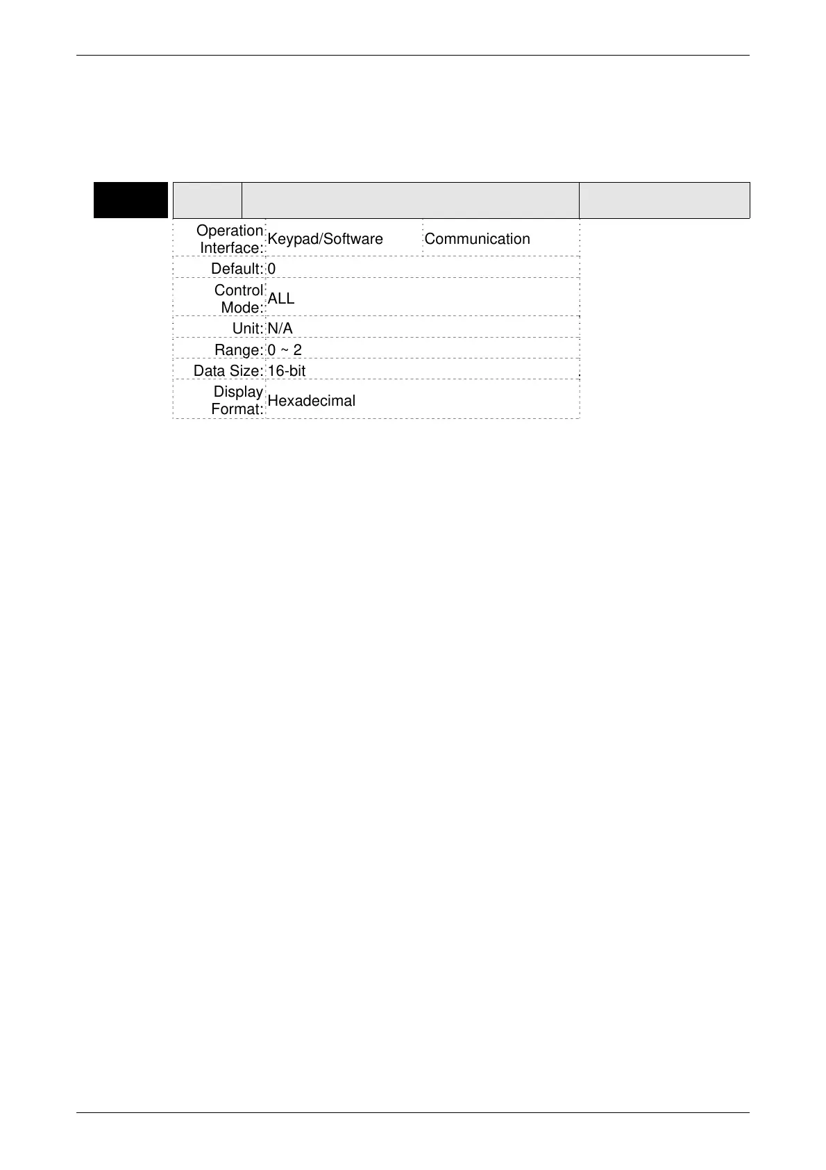
P2-32▲
AUT2 Tuning Mode Selection
Address: 0240H
0241H
Operation
Interface:
Keypad/Software Communication
Related Section:
Section 5.6,
Section 6.3.6
Default: 0
Control
Mode:
ALL
Unit: N/A
Range: 0 ~ 2
Data Size: 16-bit
Display
Format:
Hexadecimal
Settings:
0: Manual mode
1: Auto Mode [Continuous adjustment]
2: Semi-Auto Mode [Non-continuous adjustment]
Explanation of manual mode:
1. When P2-32 is set to mode#0, the setting value of P2-00, P2-02, P2-04, P2-06,
P2-07, P2-25 and P2-26 can be user-defined. When switching mode #1 or #2 to
#0, the setting value of P2-00, P2-02, P2-04, P2-06, P2-07, P2-25 and P2-26 will
change to the value that measured in #1 auto-tuning mode or #2 semi-auto tuning
mode.
Explanation of auto-tuning mode:
The servo drive will continuously estimate the system inertia, save the measured load
inertia value automatically and memorized in P1-37 every 30 minutes by referring to
the frequency response settings of P2-31.
1. When switching mode #1 or #2 to #0, the servo drive will continuously estimate
the system inertia, save the measured load inertia value automatically and
memorized in P1-37. Then, set the corresponding parameters according to this
measured load inertia value.
2. When switching mode#0 or #1 to #2, enter the appropriate load inertia value in
P1-37.
3. When switching mode#1 to #0, the setting value of P2-00, P2-04 and P2-06 will
change to the value that measured in #1 auto-tuning mode.
Explanation of semi-auto tuning mode:
1. When switching mode #2 to #0, the setting value of P2-00, P2-04, P2-06, P2-25
and P2-26 will change to the value that measured in #1 auto-tuning mode.
2. After the system inertia becomes stable (The displau of P2-33 will show 1), it will
stop estimating the system inertia, save the measured load inertia value
automatically, and memorized in P1-37. However, when P2-32 is set to mode#1 or
#2, the servo drive will continuously perform the adjustment for a period of time.
3. When the value of the system inertia becomes over high, the display of P2-33 will
VARITEL INGENIERIA ELECTRONICA S.A.
info@varitel.com - www.varitel.com - Tel. (54) 11-4243-1171 / Fax: (54) 11-4292-7545
Manuel Baliña 456, Lomas de Zamora (B1832CCJ) Buenos Aires, Argentina.