Chapter 3 Connections and Wiring ASDA-B2
3-42 Revision September 2013
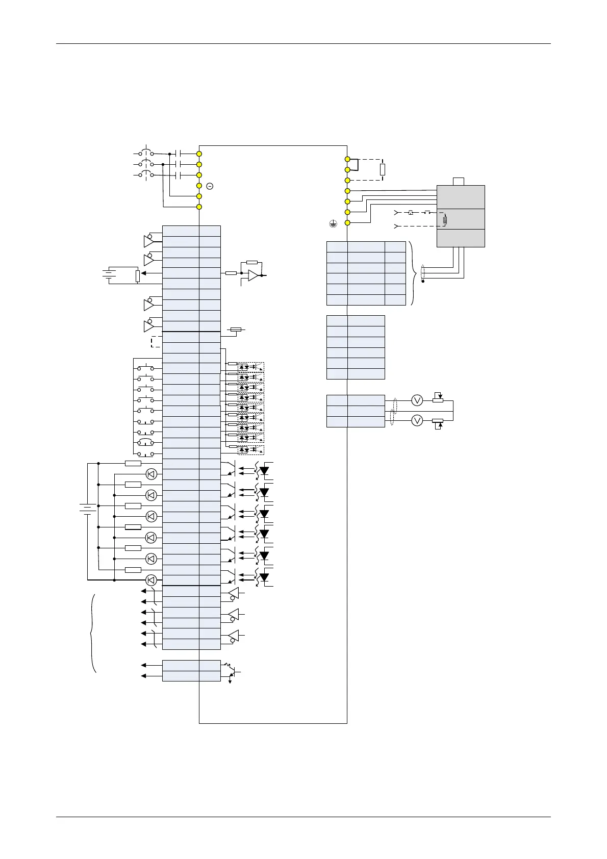
3.7 Standard Connection Example
3.7.1 Position (PT) Control Mode
OCZ
GND
44
19
10
34
8
/HPULSE
DI7
HPULSE
SIGN
/PULSE
PULSE
/HSIGN
HSIGN
DI1
VDD
COM+
COM-
DI2
DI3
DI8
DI9
DO1+
/OA
OA
OB
/OB
/OZ
OZ
/SIGN
41
43
37
39
18
19
40
42
36
38
17
T-REF
GND
/SIGN
SIGN
14
9
33
32
31
30
12
5
6
4
3
2
1
28
26
27
16
7
21
22
24
13
15
25
23
T+
T-
-
+5V
-
GND
5
Reserved
6,7
8
4
RS485+
RS232_RX
RS232_TX
GND
RS485-
-
5
6
4
3
1
2
CN2
CN3
CN1
Blue
-
-
P⊕
D
C
U
V
W
R
S
T
L1c
L2c
MC
MCCB
ASDA-B2 series
10KΩ
±10V
10KΩ
10KΩ
Red
White
Black
Green
SG
BRKREMGS
24V
Twisted-pair of
twisted-shield
cable
AC 200/230 V
Three-phase
50/60Hz
*4
*5
11
DI4
DI5
DI6
DO1-
DO2+
DO2-
DO3+
DO3-
DO4+
DO4-
DO5+
DO5-
DO6+
DO6-
0
SON
CCLR
TCM0
TCM1
ARST
CWL
CCWL
EMGS
DC 24V
1.5KΩ
1.5KΩ
1.5KΩ
1.5KΩ
1.5KΩ
SRDY
ZSPD
TPOS
HOME
ALRM
24V
1.5KΩ
0
*3
5 KΩ
5 KΩ
5 KΩ
5 KΩ
5 KΩ
5 KΩ
5 KΩ
5 KΩ
5 KΩ
Reserved
GND
MON1
MON2
3
1
2
CN5
Blue&
Black
Max. output current 3A
Voltage 50V
Servo Drive
A phase
differential signal
B phase
differential signal
Z phase
differential signal
Z phase signal
(open-collector)
Encoder
pulse
input
Regenerative
resistor
Brake
Power supply
Encoder
Red/Red&
White
Black/Black
&White
*1
Pulse input
(Line Driver)
*2
High-speed
pulse input
(Line Receiver)
SG
10KΩ
10KΩ
Twisted-pair of
twisted-shield
cable
Please note:
*1 Please refer to C3 ~ C4 wiring
diagrams in section 3.3.3.
*2 Please refer to C3 ~ C4 wiring
diagrams in section 3.3.3.
*3 Please refer to C9 ~ C12 wiring
diagrams (SINK / SOURCE mode) in
section 3.3.3.
*4 Model that under 200W has no built-
in regenerative resistor.
*5 The brake coil has no polarity.
VARITEL INGENIERIA ELECTRONICA S.A.
info@varitel.com - www.varitel.com - Tel. (54) 11-4243-1171 / Fax: (54) 11-4292-7545
Manuel Baliña 456, Lomas de Zamora (B1832CCJ) Buenos Aires, Argentina.