Do you have a question about the Delta Electronics ASDA-B2 series and is the answer not in the manual?
Guide on how to use the manual, covering contents and intended audience.
Crucial safety guidelines and handling instructions before product use.
Essential safety warnings and precautions for product installation.
Procedure to verify received product against order and check for damage.
Details on interpreting servo drive and motor model numbers and nameplates.
Table showing compatible combinations of ASDA-B2 servo drives and ECMA motors.
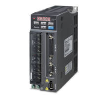
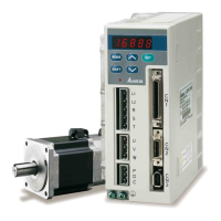
Overview of key features and components of the ASDA-B2 servo drive.
Explanation of available single and dual operating modes for the servo drive.
Guidelines for proper installation of servo drives and motors, including cable handling.
Recommendations for storing the product to maintain warranty and condition.
Environmental and operational conditions for installing servo drives and motors.
Steps for mounting drives and motors, and required spacing for ventilation.
Recommended breaker and fuse ratings for ASDA-B2 series servo drives.
Guidance on selecting and installing EMI filters for noise reduction.
Specifications and guidelines for using built-in and external regenerative resistors.
Covers peripheral connections, wiring notes, and specifications for various connectors and cables.
General wiring diagrams for different power models (400W to 3kW).
Details of CN1 connector, I/O signals, user-defined DI/DO, and wiring diagrams.
Layout and identification of CN2 drive and motor connectors for encoder connection.
Details on CN3 serial and CN5 analog monitor connectors.
Example wiring diagrams for Position (PT) control mode.
Overview of the digital keypad, display panel, and function keys.
Diagram illustrating keypad operation and mode switching logic.
Explanation of various status messages shown on the LCD display.
Basic operations like fault display, JOG, and force output control.
Covers pre-operation inspection, applying power, and initial checks before trial runs.
Procedure for performing JOG trial runs without load using the digital keypad.
Steps for conducting a speed trial run without load in speed control mode.
Methods for estimating load inertia, performing auto/semi-auto tuning, and gain adjustments.
Overview of available single and dual control modes: Position, Speed, and Torque.
Details on position control, command sources, electronic gear ratio, and loop gain.
Details on speed control, command sources, smoothing, and gain adjustments.
Details on torque control, command sources, smoothing, and input scaling.
Selecting modes and other functions like speed/torque limits and analog monitoring.
Defines parameter groups, control mode abbreviations, and symbol explanations.
Summary table of parameters for Monitor, General Use, and Control Modes.
Detailed descriptions of parameters across various groups.
Overview of RS-232 and RS-485 communication interfaces and their connections.
Settings for communication parameters like address, speed, and protocol.
Explanation of ASCII and RTU modes, data formats, and communication protocols.
Guidelines for writing and reading communication parameters.
A comprehensive list of servo drive fault codes and their descriptions.
Troubleshooting guide for common potential causes and corrective actions for drive faults.
Methods for clearing detected faults using ARST or drive restart.
Electrical and performance specifications for ASDA-B2 series servo drives.
Technical specifications for ECMA series servo motors, including low and high inertia types.
Information on overload protection functions and load/time charts.
Mechanical dimensions for ASDA-B2 servo drives and ECMA servo motors.
Details on part numbers and specifications for power connectors and cables.
Part numbers and specifications for encoder cables and connectors.
Details for I/O, Communication (RS-232/RS-485), and Analog Output connectors.
Tables showing compatible combinations of servo drives, motors, and related accessories.
Steps for basic inspection before and during operation.
General guidelines for product maintenance, cleaning, and storage.
Information on the expected lifespan of replaceable components like capacitors, relays, and fans.
| Brand | Delta Electronics |
|---|---|
| Model | ASDA-B2 series |
| Category | Servo Drives |
| Language | English |