Chapter 6 Control Modes of Operation ASDA-B2
6-6 Revision September 2013
Pulse specification
Max. input pulse
frequency
Voltage
specification
Forward
specification
High-speed pulse Line driver 4Mpps 5V < 25mA
Low-speed pulse
Line driver 500Kpps 2.8V ~ 3.7V < 25mA
Open collector 200Kpps 24V (Max.) < 25mA
D: Source of pulse command
Setting value Input pulse interface Remark
0 Open collector for low-speed pulse
CN1 Terminal Identification:
PULSE, SIGN
1 Line driver for high-speed pulse
CN1 Terminal Identification:
PULSE_D, SIGN_D
Position pulse can be input from these terminals, /PULSE (41), PULSE (43), HPULSE (38),
/HPULSE (36), /SIGN (37), SIGN (39) and HSIGN (42), /HSIGN (40). It can be an open-collector
circuit or line driver circuit. For the detail wiring, please refer to 3.6.1.
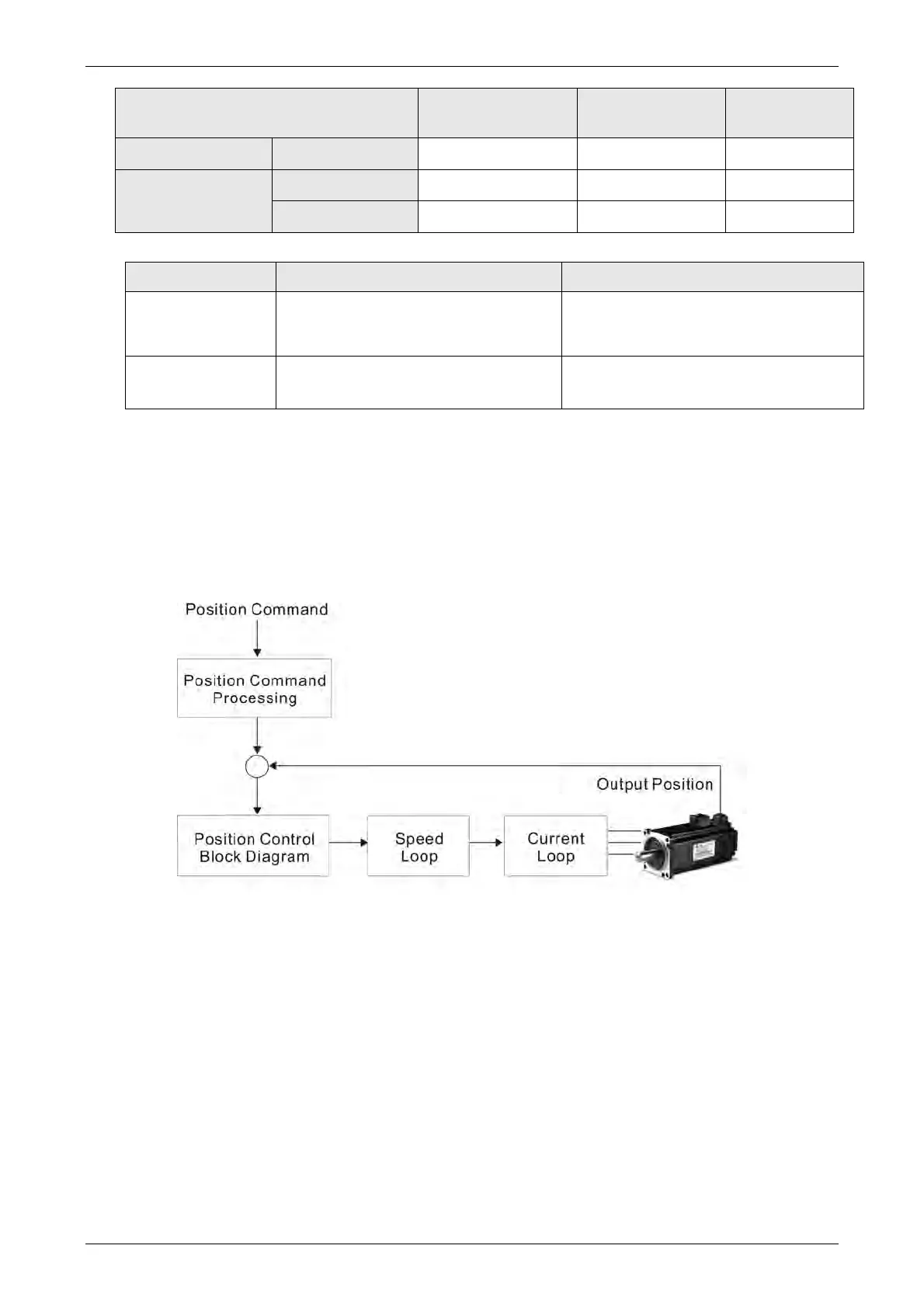
6.2.2 Structure of Position Control Mode
Basic Structure:
In order to pursue the goal of perfection in position control, the pulse signal should be
modified through position command processing and the structure is shown as the
figure below:
VARITEL INGENIERIA ELECTRONICA S.A.
info@varitel.com - www.varitel.com - Tel. (54) 11-4243-1171 / Fax: (54) 11-4292-7545
Manuel Baliña 456, Lomas de Zamora (B1832CCJ) Buenos Aires, Argentina.