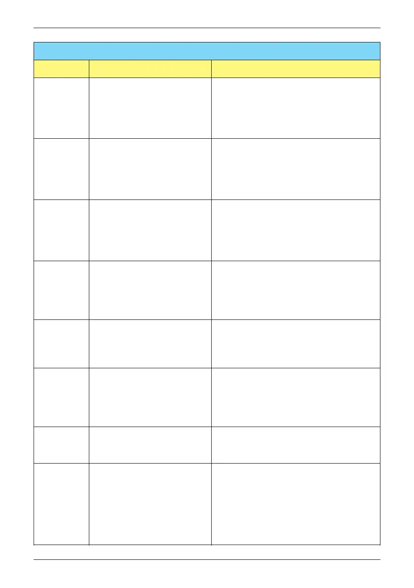
FAULT
Message Possible cause Action
HW DSP
ADC2
(F16)
1. Insufficient input power
2. Auxiliary power circuitry
malfunction
3. Detection circuit malfunction
1. Check the input voltage, must >150Vdc
2. Check the auxiliary circuitry inside the
inverter
3. Check the detection circuit inside the
inverter
HW DSP
ADC3
(F17)
1. Insufficient input power
2. Auxiliary power circuitry
malfunction
3. Detection circuit malfunction
1. Check the input voltage, must >150Vdc
2. Check the auxiliary circuitry inside the
inverter
3. Check the detection circuit inside the
inverter
1. Insufficient input power
2. Auxiliary power circuitry
malfunction
3. Detection circuit malfunction
1. Check the input voltage, must >150Vdc
2. Check the auxiliary circuitry inside the
inverter
3. Check the detection circuit inside the
inverter
1. Insufficient input power
2. Auxiliary power circuitry
malfunction
3. Detection circuit malfunction
1. Check the input voltage, must >150Vdc
2. Check the auxiliary circuitry inside the
inverter
3. Check the detection circuit inside the
inverter
HW Red
ADC1
(F18)
HW Red
ADC2
(F19)
HW Eff.
(F20)
1. The calibration is incorrect
2. Current feedback circuit is
defective
1. Check the accuracy of current and power
2. Check the current feedback circuit
inside the inverter
HW
COMM1
(F23)
1. DSP is idling
2. The communication
connection is disconnected
3. The communication circuit
malfunction
1. Check reset and crystal in DSP
2. Check the connection between DSP
and COMM
3. Check the communication circuit
HW
COMM2
(F22)
1. Red. CPU is idling
2. The communication
connection is disconnected
1. Check reset and crystal in Red. CPU
2. Check the connection between Red.
CPU and DSP
Ground Cur.
(F24)
1. PV array insulation fault
2. Large PV array capacitance
between Plus to Ground or
Minus to Ground
3. Either side of boost driver
or boost choke malfunction
4. Detection circuit malfunction
1. Check the insulation of Solar inputs
2. Check the capacitance (+ <-> GND &
- <-> GND), must < 2.5uF. Install a
external transformer if necessary
3. Check boost driver & boost choke
4. Check the detection circuit inside the
inverter
60
Error message and Trouble Shooting

 Loading...