6159932010-09
45 / 60
English
CVIC - MODCVIC - MULTICVIC
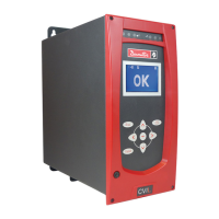
Appendix - PC wiring diagram
Diagram of PC cable number 6159170470
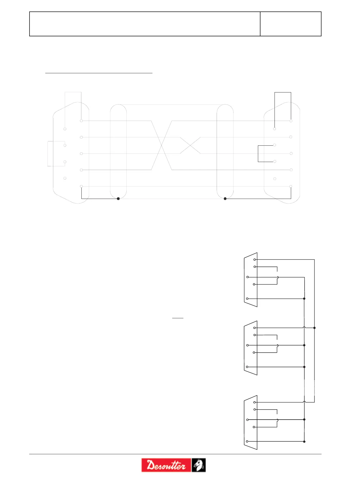
Appendix - Synchronising several CVIC controllers
To synchronise several CVIC version «H» controllers, you must:
- allocate the synchro in and synchro out signals to unused inputs and
outputs.
- connect the «synchro» signals of the controllers and program a
«Synchr. waiting» phase for each controller.
Warning:
The 0 Volt (contact 1) of the 37-point connectors of each controller are
connected to eachother.
All other signals (cycle number, run...) must be connected to each controller.
Example of connection
diagram:
24/25/26/27
28/32/33/36
1
17
0 V
4
1
17
0 V
4
1
17
0 V
4
3/5/6/7
ontroller 1
ontroller 2
ontroller 3
synchro in
synchro out
synchro in
synchro out
synchro in
synchro out
9
8
7
6
5
4
3
2
1
T D
R D
D S R
G N D
D T R
C T S
R T S
D C D
D C D
R D
T D
D T R
G N D
R T S
C T S
D S R
6
7
8
9
1
2
3
4
5
B L A C K
W H I T E
B R O W N
B L U E
R E D
S u b D 9 c o n t a c t s o c k e t
P C s i d e
B L U E
S u b D 9 c o n t a c t s o c k e
c o n t r o l l e r s i d e
B L A C K
W H I T E
B R O W N
R E D