6159932010-09
7 / 60
English
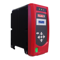
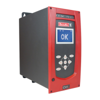
CVIC - MODCVIC - MULTICVIC
2 - Installation and Installation Instructions
Mains voltage
All the controllers of the range (CVIC and MODCVIC) can operate equally from 115V to 230V ± 10%/ 50 to 60Hz without
adjustment and without fuse change.
The CVIC controllers are supplied with single-phase current. The MODCVIC modules are supplied with three-phase current.
Power
The average power required for a CVIC<->2 system is approximately 0.500 kW.
The average power required for a CVIC<->4 system is approximately 0.650 kW.
Circuit-breakers
Should circuit-breakers be installed at line head, we recommend that you select equipment with the following specifications:
For CVIC controller
- Single-phased 230V 4A - curve C
- Single-phased 115V 6A - curve C
For MODCVIC module
- Three-phase 230V0.75 kVA - Thermal 2.5 to 4 A - Magnetic > 45 A
- Three-phase 115V0.75 kVA - Thermal 4 to 6.3 A - Magnetic > 45 A
Grounding
Make sure that the controller is grounded via a protective conductor. It is recommended to secure the controller to a grounded
metal mounting insofar as possible, in order to strengthen immunity to electromagnetic interference.
Tool cable
Although our cables are designed to work under drastic conditions, we recommend that you check the following points for
longer service life:
- Bending radii should not be lower than 10 times the cable diameter.
- Friction with the outer sheath should be restricted.
- Any direct pull on the cable should be avoided.
Installation Instructions for MODCVIC
To be compliant with EMC directives, MODCVICs should be wired in a cabinet in accordance with the following
recommendations:
Cabinets:
Electric equipment shall be located in a cabinet with minimum IP4X protection level, ref. EN 60529. Protection against
electric shocks from either direct or indirect contact shall be provided in compliance with EN 60204-1. Door interlocks and
keys will be used.
Input filter:
If a transformer is included in the unit, insert a three-phase filter (Schaffner type FN351) at the secondary winding of the
servodrive mains transformer. This filter should be fitted on a grounded metal mounting, as close as possible to the
transformer.
If the mains supply is used directly, insert a three-phase filter (Schaffner type FN251) in the mains. This filter should be fitted
on a grounded metal mounting, as close as possible to this voltage input.
Dimensioning of the filter:
For the dimensioning of the filter, there should be 3Aeff per channel with three-phase 230V and 6 Aeff per channel with three-
phase 115V. Multiply this value by the number of channels to obtain the filter nominal amperage.