User Manual DEV 2190
Copyright DEV Systemtechnik GmbH 2009-2017 15
The color of the power line status LEDs "Power 1" (1) and "Power 2" (2) is usually green
meaning that the device is supplied with primary voltage via the corresponding
power plug. If it is detected that there is not sufficient primary voltage at a power
plug, the corresponding LED turns to red.
The fan functionality is monitored, i.e. the "Fan" status LED (3) being green indicates
the fan to be ok; if the fan speed is too low, the LED turns to red.
The temperature status LED "Temp" (4) turns to red if the CPU module reports the
temperature to be too high, otherwise it is green.
A red "Alarm" LED (5) indicates a number of pending and not acknowledged errors
(chapter 5.4.5); otherwise, the "Alarm" LED is green.
If the yellow operation mode status LED "Remote" (6) is on, the device is in
Remote Mode (or in Auto Mode, see below); the LED being off indicates
Local Mode, please refer to chapter 5.1 for more information on this subject.
Pressing and holding the push button labeled "Local" (7) (e.g. by using a ballpoint
pen) for approximately one second, changes the operation mode (indicated via the
"Remote" LED).
Note that if the DEV 2190 is equipped with redundancy switching functionality, the
switching from Local Mode via the "Local" push button toggles to the preceding
mode (Remote Mode or Auto Mode) which was activated, before the device had
been switched to Local Mode. The explicit activation of either Remote Mode or
Auto Mode can be performed via Web Interface (chapter 5.4.2) or via SNMP
(chapter 5.5.4.3.1).
Note:
After power-up of the device, all LEDs of the fan & monitoring module are
blinking (red/green and yellow/off), indicating that the module initialization is
not completed. In addition, the sound of the fan varies during this phase until
the temperature control algorithm is started.
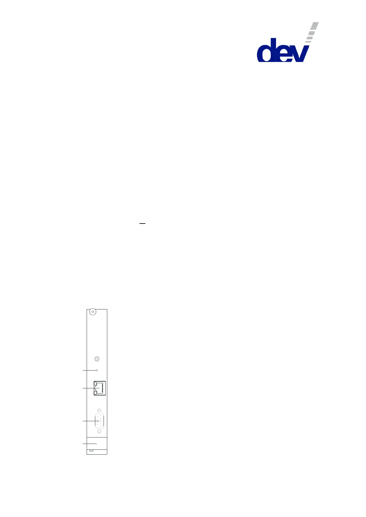
3.2.3 CPU Module
4
1
2
3
1 Reset Button
2 Ethernet Connector
3 Com Connector
4 Extraction Lever
Reset
Ethernet
Com
CPU Module
The CPU module manages the monitoring and control
functionality of the device and is located at the rear side
of the chassis left to the faceplate holding the power
plugs and the grounding bolt.
Normally, the "Reset" push button (1) is not to be
operated at all. It is to be actuated only in case that a
change on the device configuration was applied, or in
very rare cases that the remote
communication/operation does not behave normally or
does not work any longer. For a reset press and hold (e.g.
with a ballpoint pen) the reset button for approximately
three seconds. After a reset, the remote functionality
should be recovered. Note that a reset does not interrupt
the signal transmission.
The RJ-45 connector labeled "Ethernet" (2) provides an
Ethernet interface used for the communication via
Web Interface or via SNMP. Please refer to chapter 4.4.2
for the configuration of the interface.