User Manual DEV 2190
92 Copyright DEV Systemtechnik GmbH 2009-2017
6 Error Indication
The indication of an error is realized via hardware, i.e. via red LEDs and additionally
via software, i.e. via Web Interface, via an SNMP trap, or by polling the
corresponding SNMP object(s). The hardware indication via LEDs is described in
chapter 3.2. The indication via Web Interface is subject of chapters 5.4.3 & 5.4.5;
the indication via SNMP is explained in chapters 5.5.4.1 & 5.5.4.4. The software
error indication (i.e. the error codes) is described in the following.
6.1 Software Error Indication
The device is capable to detect several types of errors that are reported to the Web
Interface and to the M&C system. Either the M&C system has to poll the device for
these errors or it is informed via an alarm trap, assuming that the specific SNMP
trap is enabled.
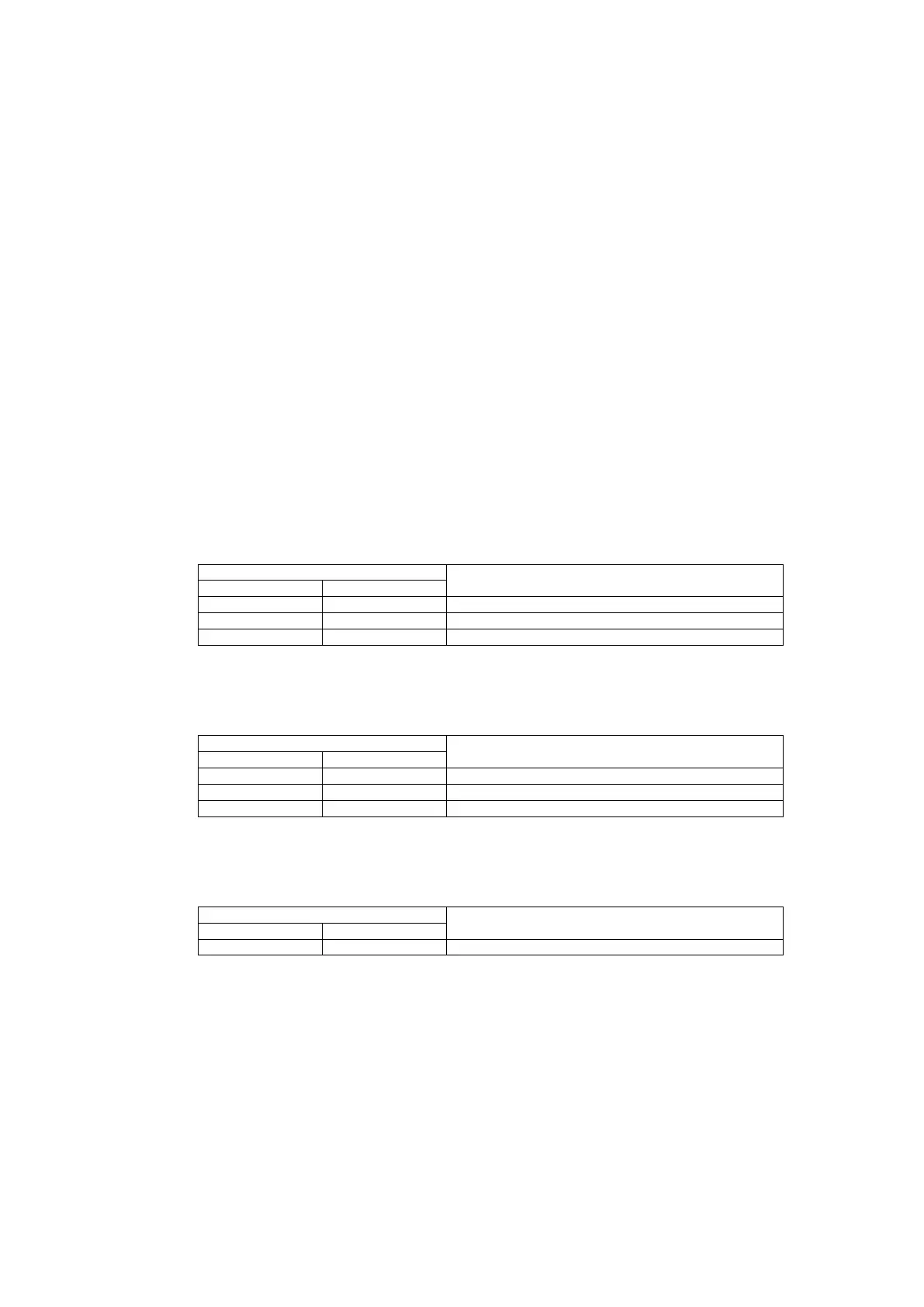
6.1.1 Power Errors
The power supply of the device is monitored. In case that a power line error, that a
defective power supply module, or that a communication problem with the power
module is detected, a corresponding error is reported.
Power Line [i] (i = {1…2})
Power Supply [i] (i = {1…3})
Power Module [i] (i = {1…3})
6.1.2 Fan & Monitoring Module Errors
The speed of the fan and the fan & monitoring module functionality itself are
monitored and a corresponding error is reported in case of a failure.
6.1.3 Switch Errors
If equipped with redundancy switching functionality, the redundancy switch
modules are monitored. A corresponding error is reported in case of a failure.
Switch Module [i] (i = {1…5})