User Manual DEV 2190
Copyright DEV Systemtechnik GmbH 2009-2017 45
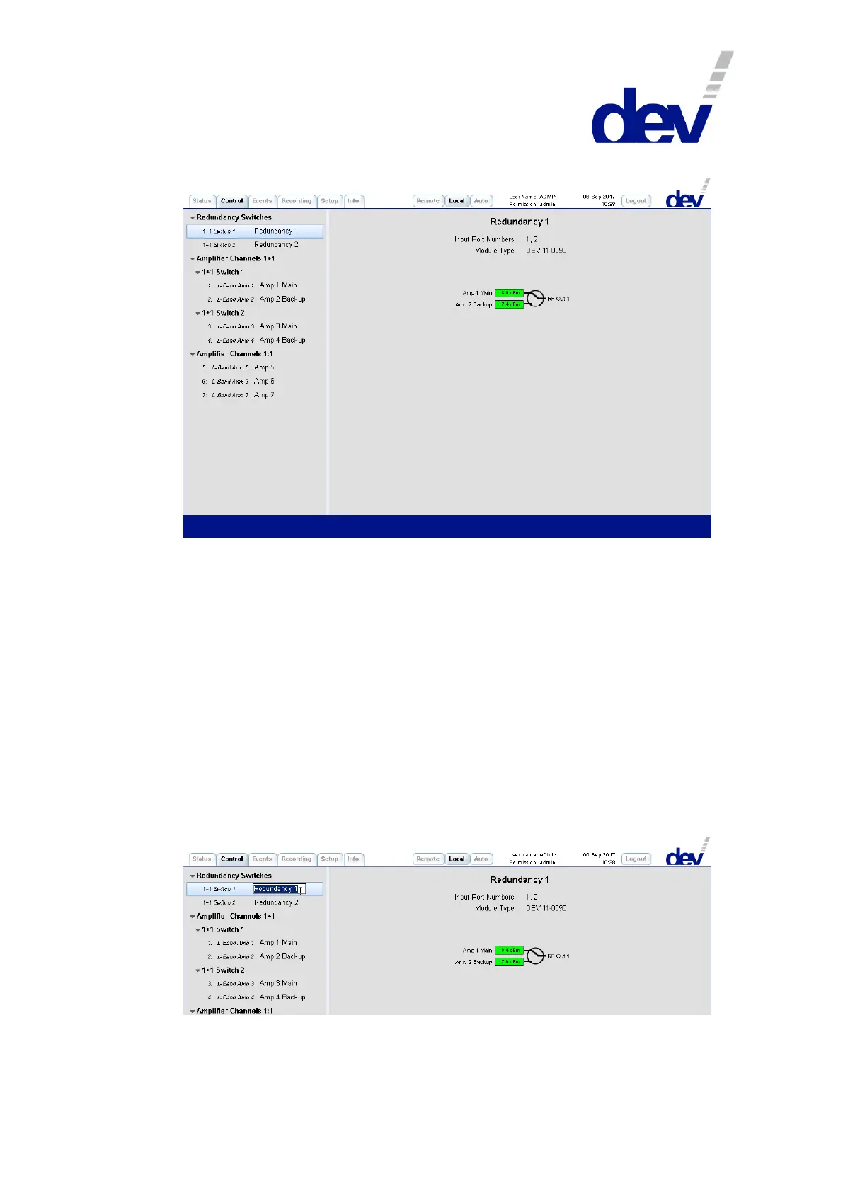
5.4.4 Control Tab
On the left side, the Control Tab contains a number of items in order to branch to
the different functionalities of the device. The number and the type of functionality
items depends on the device configuration, here the functionality items
"Redundancy Switches" and "Amplifier Channels 1+1" show up first, since this DEV 2190 is
equipped with (two) redundant amplifier options. Then the functionality item
"Amplifier Channels 1:1" appears, since there are installed (three) amplifier modules in
1:1 configuration in addition.
The left column within a functionality item refers to the module functionality and
to the entity counting (e.g. "1: L-Band Amp 1"). The name in the right column is a
descriptive designator. Default is e.g. "Redundancy 1" for the switch functionality of the
first redundancy unit, and default is e.g. "Amp 1 Main" & "Amp 2 Backup" for the two
amplifier modules serving as the main and as the backup channel of the first
redundancy unit; and default is here e.g. "Amp 6" for the sixth amplifier module (in
1:1 configuration).
A descriptive designator can be edited by double-clicking the specific item:
Note that on the right side in a switch panel (!) the port names of the
corresponding switch (here: "Amp 1 Main", "Amp 2 Backup", and "RF Out 1") can be edited in
the same manner.