User Manual DEV 2190
28 Copyright DEV Systemtechnik GmbH 2009-2017
4 Installation Instructions
4.1 Scope of Delivery
1 * DEV 2190 equipped with amplifier options, distribution options,
combiner options, IRD controlled switch options and extensions,
redundant amplifier options, and other options
as ordered
1 * User Manual (this document)
4.2 Installation of the Product
4.2.1 Mechanical Assembly of the Product
Please refer to the warnings in chapter 2.3 regarding the mechanical integration of
the product. For the assembly in a 19" rack the rack slots must be prepared with
rails for the chassis. After inserting the chassis in the rack, fix the chassis with four
screws to the rack at its rack mount flanges.
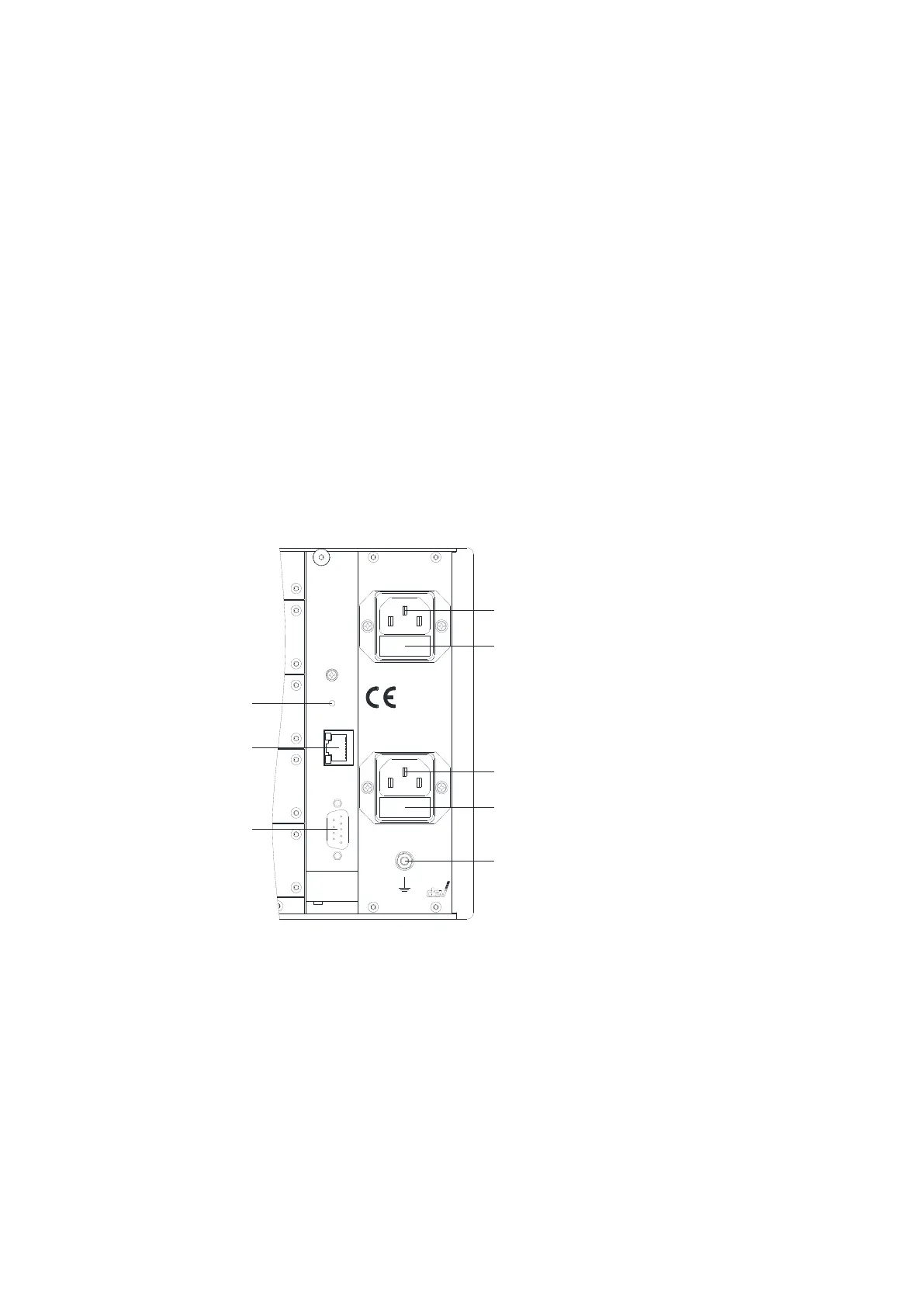
4.2.2 Grounding, Data Cables and Power Connection
GND
P1
F2
P2
F1
Eth
Res
Com
Reset
Ethernet
Com
Supply 1 - Fuse 6 A T
Supply 2 - Fuse 6 A T
W ARNIN G :
Disconnect p ow e r before o p enin g !
100...240 V
50...60 Hz
100 VA
For the warnings with respect to "Grounding, AC Connection, Cables" please refer
to chapter 2.3.
The chassis needs to be connected to the 19" rack via a ground wire. The grounding
bolt is located on the right at the rear side of the product:
Take off the upper nut and the first washer of the grounding bolt (labeled GND in
the figure above) and connect the grounding cable, which must have a ring tongue
terminal matching for the M4 fastening bolt. After that, the washer and the nut
have to be tightened again.
At the CPU module (chapter 3.2.3), establish the external Ethernet connection by
plugging an Ethernet cable from your network to the "Ethernet" port of the CPU
module (Eth).