User Manual DEV 2190
16 Copyright DEV Systemtechnik GmbH 2009-2017
The connector labeled "Com" (3) is a serial interface, which can be used for the basic
network setup (chapter 4.4.2.2). The serial interface configuration is subject of
chapter 4.4.1. The extraction lever (4) simplifies the removal of the CPU module.
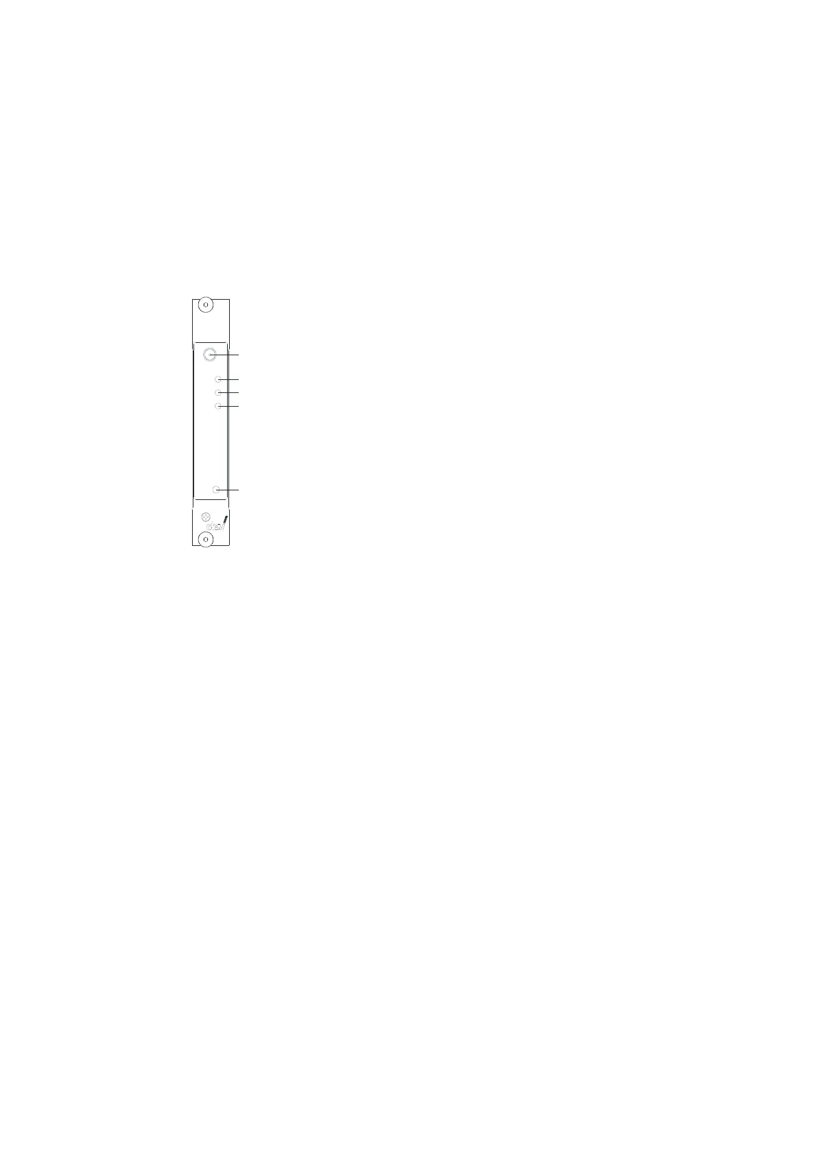
3.2.4 Amplifier Modules
Up to sixteen amplifier modules can be installed within the DEV 2190. Though the
physical appearance of the front side of all amplifier modules is identical, there are
applied amplifier modules with one or two RF outputs please refer to chapter 9.
2
5
3
4
1
1 M onitor Port
2 O peration LED
3 RF LED
4 Bias LED
5 Bias B utton
Amplifier M odule
L-B and Am p.
Mon
Bia s
RF
Op.
Bia s
An amplifier module provides a monitoring port labeled "Mon" (1). The operation
status LED labeled "Op." (2) is on and green if the module is supplied with power
and if the amplifier circuits are working normally. The LED turns to red if circuits of
the module are detected as being defective, i.e. the module has to be exchanged. If
the LED is off, this indicates that no power is applied to the module.
With the integrated RF level monitoring functionality, the aggregated power level
of the RF signal is measured and compared with a threshold level. If the RF signal
level is below the threshold level, an alarm is triggered. The status is indicated via
the "RF" LED (3): green means ok, red indicates the signal level to be below the RF
threshold level. Additionally, via Web Interface (please refer to chapters 5.4.3 &
5.4.4.2) and via SNMP (chapters 5.5.4.3.9.5 & 5.5.4.3.9.18) the RF level status is
indicated and the RF threshold level can be modified.
The amplifier modules provide LNB power with current monitoring, i.e. the
modules are prepared to feed DC current through the RF input port in order to
supply LNBs or inline amplifiers with power. The "Bias" push button (5) is used to
turn on or off the LNB power supply (in VL mode, please refer to the note below).
The (enabled) "Bias" push button can be operated in Local Mode, only; alternatively,
the LNB power can be switched in Local Mode via Web Interface (chapter 5.4.4.2)
and in Remote Mode via SNMP (chapter 5.5.4.3.9.8).
The current monitoring feature is applied for the surveillance of the current fed by
the LNB power supply. I.e. the measured current delivered by the RF input port is
compared with a lower and with an upper limit. The status of this alarm is indicated
via the "Bias" LED (4): If the LNB power supply is turned off, the LED is off. If the LNB
power supply is turned on and the supplied current is within limits, the LED is
green. If the lower limit (no or not enough current) or the upper limit (too much
current is drawn) is exceeded, the LED is red.