User Manual DEV 2190
Copyright DEV Systemtechnik GmbH 2009-2017 9
3 Product Description
The Managed L-Band Distribution System DEV 2190 provides different communica-
tion features and can be equipped very flexible, thus enabling numerous different
RF signal distribution configurations.
At the front side the rack mountable 4 RU chassis provides space for up to 16 am-
plifier modules. At the rear side, the chassis provides horizontal slots for the distri-
bution of RF signals. These slots can be equipped with splitters, with combiners, or
with IRD controlled switches.
In the following, the general product structure is shown and the available options
are explained which can be installed in the DEV 2190. After that, the several
modules are described, followed by a few configuration examples.
3.1 Features and Options
3.1.1 Product Structure
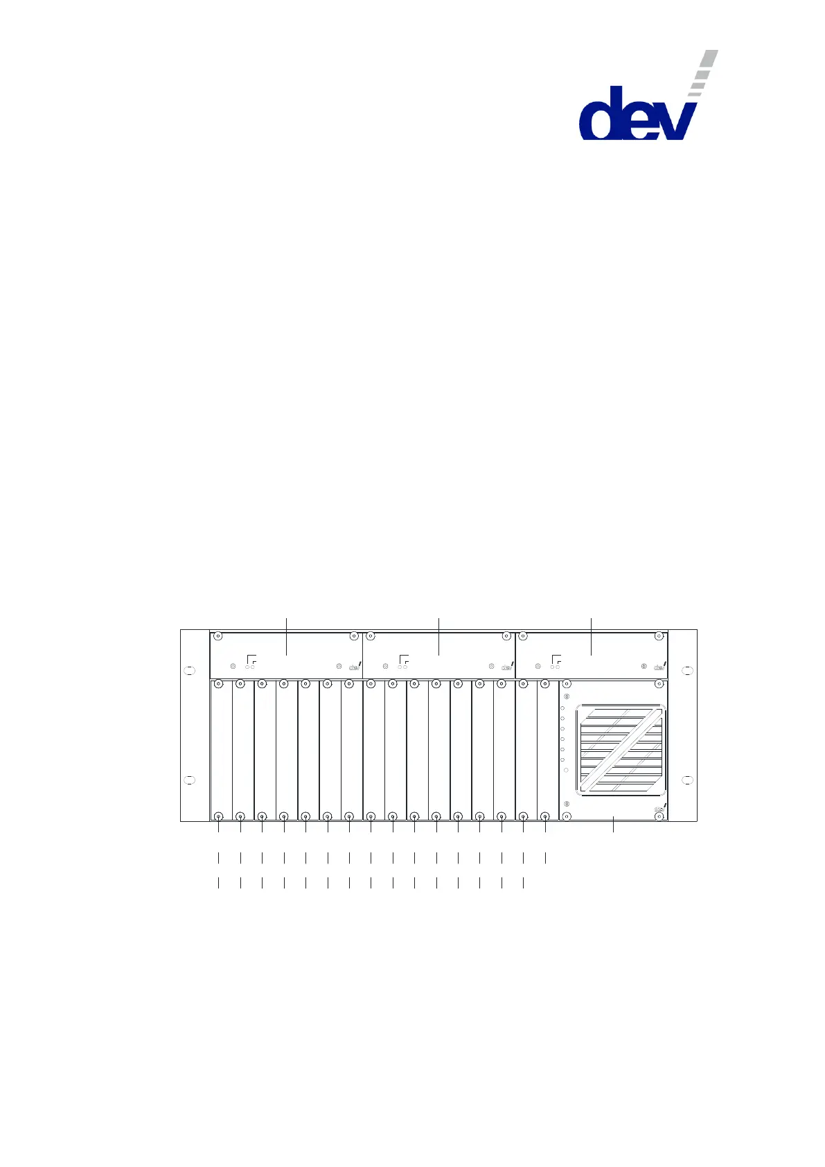
At the front side, the DEV 2190 is equipped with up to three hot-pluggable power
supply modules (labeled PS1…PS3 in the figure below, the power supply modules
are explained in chapter 3.2.1) which are assembled horizontally above the other
modules.
A temperature controlled fan & monitoring module (F, chapter 3.2.2) installed at
the right provides status information and permits to change the operation mode of
the device.
The available slots (1…16) for amplifier modules (chapter 3.2.4) and for redundancy
switch modules (chapter 3.2.5) are located left to the fan & monitoring module.
1 2 3
4 5
6
7
8 9 10 11 12 13 14 15 16
F
Slot
PS1 PS2 PS3
11:1 2 3
4 5
6
7
8 9 10 11 12 13 14 15 16
1+1
S1
M1
S2
M2 M3B2 M4B3 B4
S4
B5
S5
B1
S3
M5
Po we r 1
Po we r 2
Fa n
Te mp
Al arm
R emote
Lo ca l
12-00 20
Operation
Failure
Power S upply
12-00 20
Operation
Failure
Power S upply
12-00 20
Operation
Failure
Power S upply
Without applied redundancy options (this type of configuration is also named "1:1"
in the following), the amplifier modules are installed and counted from left to right.
If the chassis is equipped with redundant amplifier options (this type of configu-
ration is named "1+1" in the following), this requires the installation of redundancy
switch modules (Si) in addition to the main (Mi) and to the backup (Bi) amplifier
modules. If there are installed additional amplifier modules in 1:1 configuration,
these modules are located right to the last backup (Bi) amplifier module.