User Manual DEV 2190
Copyright DEV Systemtechnik GmbH 2009-2017 23
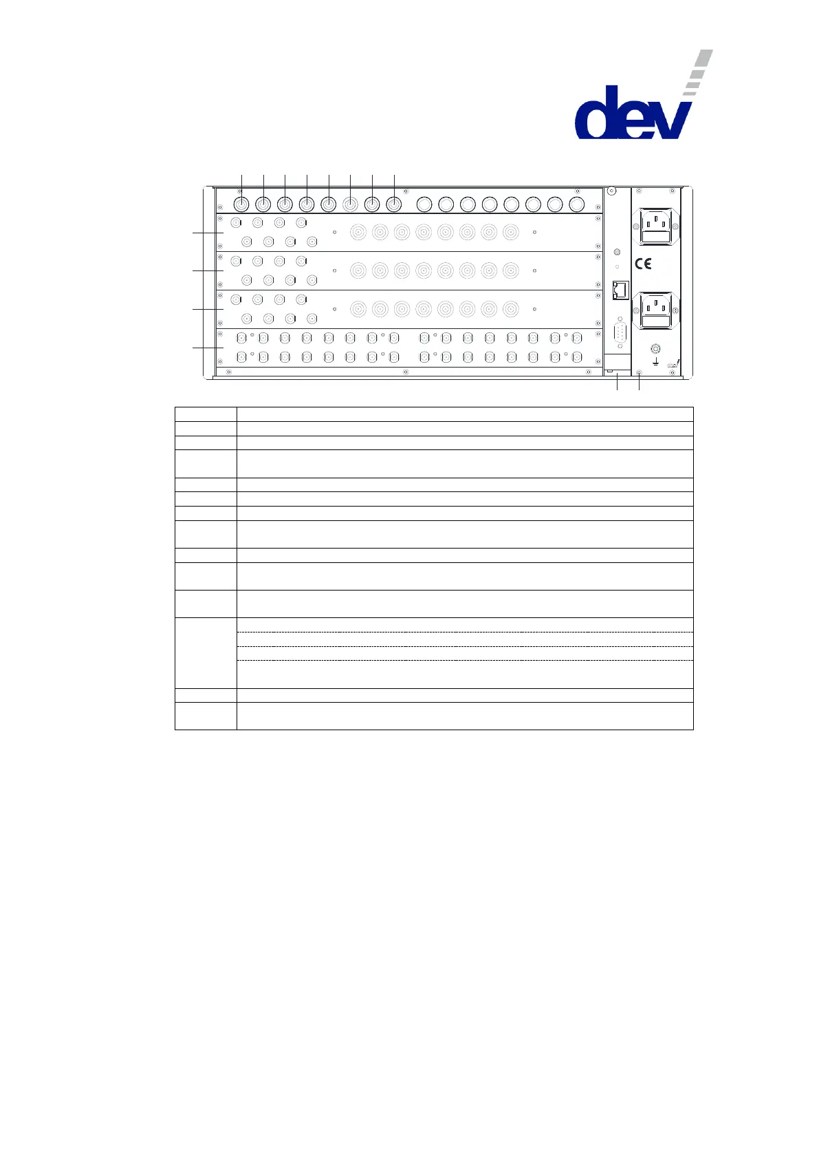
Rear View:
1 2
3
4
5 6
7
8
C
P
S1
S2
S3
S4
Res et
Etherne t
Com
1615
14
13
1211
1098
7
65
4
3
21
1
9 10
11 12
13
14
15 16
2
3
4
8
7
65
1
9 10
11 12
13
14
15 16
2
3
4
8
7
65
1
9 10
11 12
13
14
15 16
2
3
4
8
7
65
8
7
65
4
3
21
8
7
65
4
3
21
8
7
65
4
3
21
8
7
65
4
3
21
Sup ply 1 - Fus e 6 A T
Sup ply 2 - Fus e 6 A T
W A RN ING :
D isco nn ect po wer be fore op en ing!
10 0.. .240 V
50 ...60 H z
10 0 V A
Input module Slot 1 (for IRD controlled switch 1 HH)
Input module Slot 2 (for IRD controlled switch 1 VH)
Input module Slot 3 (for IRD controlled switch 1 HL)
Input module Slot 4 (for IRD controlled switch 1 VL)
Input module Slot 5 (for IRD controlled switch 2 HH & S4, first 1:8 splitter)
Input module Slot 6 (for IRD controlled switch 2 VH & S4, second 1:8 splitter)
Input module Slot 7 (for IRD controlled switch 2 HL & S4, third 1:8 splitter)
Input module Slot 8 (for IRD controlled switch 2 VL & S4, fourth 1:8 splitter)
IRD controlled switch 1, outputs 1…16 (inputs: modules Slot 1…4)
IRD controlled switch 1, outputs 17…32 (inputs: modules Slot 1…4)
IRD controlled switch 2, outputs 1…16 (inputs: modules Slot 5…8)
First 1:8 splitter (upper row, left) (input: module Slot 5)
Second 1:8 splitter (upper row, right) (input: module Slot 6)
Third 1:8 splitter (lower row, left) (input: module Slot 7)
Fourth 1:8 splitter (lower row, right) (input: module Slot 8)
Power inlets, grounding bolt