User Manual DEV 2190
Copyright DEV Systemtechnik GmbH 2009-2017 25
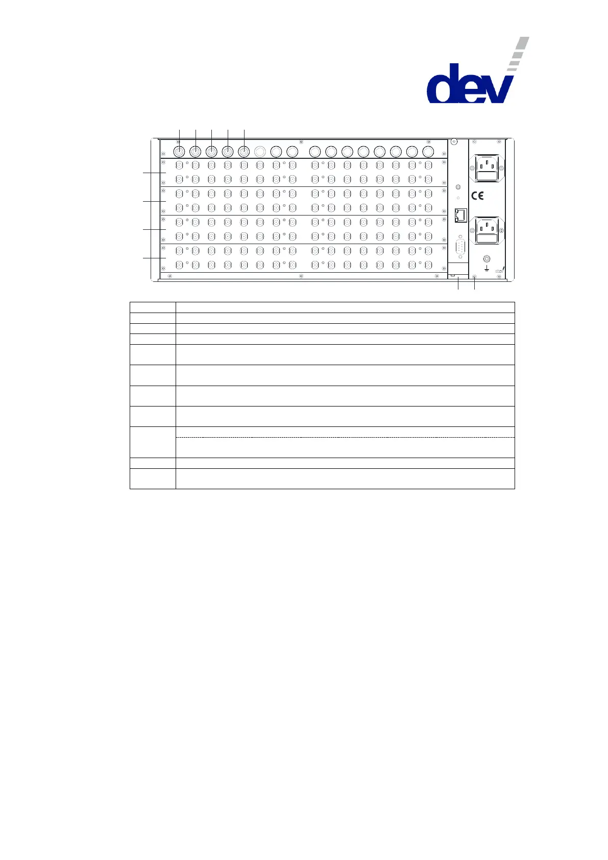
Rear View:
1 2
3
4
5
C
P
S1
S2
S3
S4
Res et
Etherne t
Com
1615
14
13
1211
1098
7
65
4
3
21
1615
14
13
1211
1098
7
65
4
3
21
3231302928
27
2625
24
23
2221
201918
17
1615
14
13
1211
1098
7
65
4
3
21
3231302928
27
2625
24
23
2221
201918
17
1615
14
13
1211
1098
7
65
4
3
21
323130
2928
27
2625
24
23
2221
201918
17
1615
14
13
1211
1098
7
65
4
3
21
1615
14
13
1211
1098
7
65
4
3
21
Sup ply 1 - Fus e 6 A T
Sup ply 2 - Fus e 6 A T
W A RN ING :
D isco nn ect po wer be fore op en ing!
10 0.. .240 V
50 ...60 H z
10 0 V A
Input modules Slot 1…3 (for redundancy unit 1)
Input modules Slot 4…6 (for redundancy unit 2)
Input modules Slot 7…9 (for redundancy unit 3)
Input modules Slot 10…12 (for redundancy unit 4)
Input modules Slot 13…15 (for redundancy unit 5)
1:32 splitter (input: redundancy unit 1, modules Slot 1…3)
1:32 splitter (input: redundancy unit 2, modules Slot 4…6)
1:32 splitter (input: redundancy unit 3, modules Slot 7…9)
First 1:16 splitter (upper row) (input: redundancy unit 4, modules Slot 10…12)
Second 1:16 splitter (lower row) (input: redundancy unit 5, modules Slot 13…15)
Power inlets, grounding bolt