User Manual DEV 2190
48 Copyright DEV Systemtechnik GmbH 2009-2017
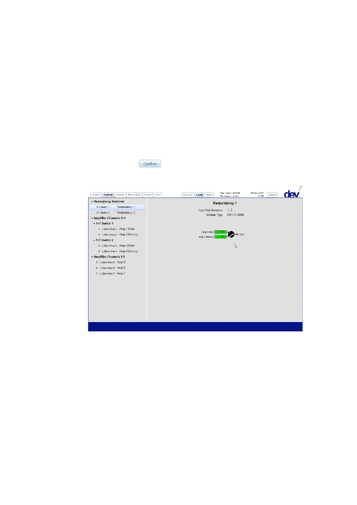
2) Within the second section the switching of the redundancy switch can be
performed.
The screenshot above shows in the middle the measured RF levels of the main
channel (here: "Amp 1 Main") and of the backup channel (here: "Amp 2 Backup") on
the left side. The green background implies that the level is above the
individual RF threshold; otherwise, it is red.
The background color of a port rectangle appears in gray if it is disabled (e.g. by
deactivating the corresponding "Surveillance Enable" check box).
The switching of the redundancy unit is performed as follows:
As shown in the screenshot above, a click on the circle between the
representation of inputs and output causes two additional buttons to appear.
After a click on the button in Local Mode (!), the actual switching is
performed and the new switching position (the switch is switched to the
backup channel) is shown: