6/ INSTALLATION
OPERATOR'S MANUAL
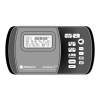
Dj SEED MANAGER® SE PLANTER MONITOR
BENCHMARK Series® 11001-1218-200112 Rev A
B. CONSOLE
HARNESS
INSTALLATION
The J1 connector on the back of the
console connects all input and output
signals to the Seed Manager® SE
console.
The primary tractor harness is shown in
Figure 3. This harness contains connec-
tors for a ground speed sensor (digital),
a ground speed sensor (reluctance),
system power, and P1 and P2 Bus
connectors. A secondary module
harness is used to connect to P1 and/or
P2.
For systems that contain a J2 connector, a
separate accessory harness will contain a
RS-232 connector for PC/GPS applica-
tions.
The following procedures describe
installing the primary (J1) harness from
the rear of the console to the tractor
hitch:
STEP 1
Route the primary harness from J1 on
the console rear to the rear of the
tractor, near the hitch. Route it on the
Figure 3
Primary Tractor Harness
46682-0132
Mates with Reluctance
Ground Speed Sensor
 Loading...