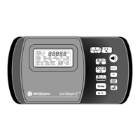
OPERATOR'S MANUAL
INSTALLATION/ 9
Dj SEED MANAGER® SE PLANTER MONITOR
BENCHMARK Series® 11001-1218-200112 Rev A
C. IMPLEMENT
HARNESS /
MODULES /
SENSORS
The Seed Manager® SE system uses any
combination of three basic module types,
each with their own specific harness
configurations. There are 12 Row
Material Flow Modules, 16 Row Material
Flow Modules, and Shaft Speed
Modules. A single Bus cable connects to
each module, then serially (daisy chains)
connects to following modules. The
primary harness divides into two halves
at the implement hitch (P1 and P2). The
following requirements must be ob-
served when connecting modules to the
bus:
1. A maximum of six Material Flow
Modules can be connected to the bus.
2. Only one Shaft Speed Module may be
connected to the bus. The Shaft Speed
Module may be connected anywhere on
the bus that is convenient. It can be
connected to either P1 or P2.
3. No more than three Material Flow
Modules can be connected to P1 or P2.
4. Any combination of 12 Row or 16 Row
Material Flow Modules may be used.
The order in which the Material Flow
Modules are connected and their
position on the toolbar or implement is
important to note. The Material Flow
Modules are identified by the console as
b1, b2, . . . bn (where n is the total
number of Material Flow Modules
connected). The order in which the
console identifies the modules depends
upon how they are connected to the bus.
The following figures show example
system configurations and how the
Console identifies the modules connect-
ed for each configuration. Note order of
the modules in relation to how they
connect to the bus.

 Loading...