63
PULSE MX
Sort:
tidies the list of events based on a growing smpte times (valid only in Edit mode)
Delete:
deletes, after conrmation, all selected events (valid only in Edit mode)
New (from the context-specic Menu) Deletes the current list and prepares for the creation of a new
list.
Save as (from the context-specific Menu):
saves (duplicates) the current list under a new name
Open: (from the context-specific Menu):
opens the browser to load a list which had previously been saved on the disk.
IMPORTANT: before putting a list in the play status make sure it is tidy; otherwise, press the Sort button; if
the list is not tidy, the correct execution of events is not guaranteed. Play status is maintained even after
exiting the Smpte window.
Creating a list of events
When the Smpte window is in Record mode, any event generated by the console (for example, sending
a trigger to a playback) is added to the queue of Smpte events in a new line. If the Smpte source is not
connected, the new event has 0-0-0-0 activation time; the Smpte source is connected, the activation
time is read by the Smpte timecode:
• Cue trigger
• Cue list release
• Release of all Qlists
• Change page
Usually the Record stage is followed by an Edit stage during which the activation times are amended and
it is often necessary to return to the Record mode in order to add any missing events.
Execution of the list of events
To execute the list of events, set it to Play mode. In order for the list to be correctly processed, it has to be
in the right chronoplaybackical order: the Sort button, when the list is in Edit mode, serves this purpose.
In Play mode, the received timecode is constantly compared against the events on the list which are
activated when necessary.
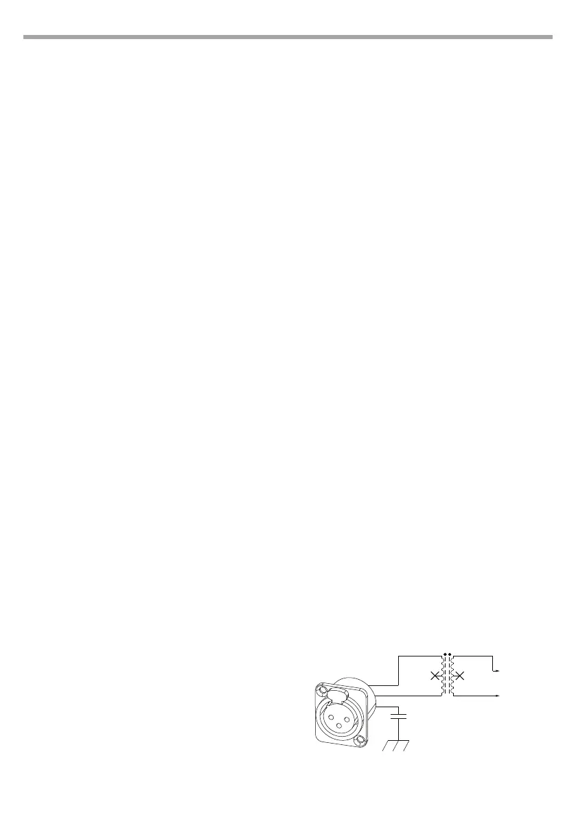
Smpte Connection
The Smpte input of the console is made up of an
audio transformer connected to pins 2 and 3 of the
XLR connector (See picture below) and is suitable
for directly connecting a Smpte device with dier-
ential output. The galvanically isolated structure of
the input allows to use a Smpte source with a single-
ended output by connecting the hot wire and the
signal mass respectively to pins 2 and 3 of the XLR
connector.
SMPTE input section schematic
After connecting, verify
that the Smpte frames
are scrolling on the status
bar in the top right-hand
corner of the Smpte
window.
1
2
3
ln
CHASSIS
TY-141P
Audio transformer
To SMPTE
Receiver
SMPTE INPUT SECTION
1
2
3