ICS-90 Ion Chromatography System
2-10 Doc. 031851-05 12/04
accurate flow. Pressure limits are used to detect high or low pressure
conditions that might require the pump to be shut down.
The system backpressure should remain consistent. A significant increase
in backpressure indicates a blockage in the liquid lines. A significant
decrease in backpressure may indicate leaks or decreased pump flow due
to an unprimed pump or insufficient eluent.
Injection Valve with Sample Loop
The injection valve is a six-port, electrically-activated Rheodyne valve. A
10-µL sample loop (P/N 042857) is installed on the valve at the factory.
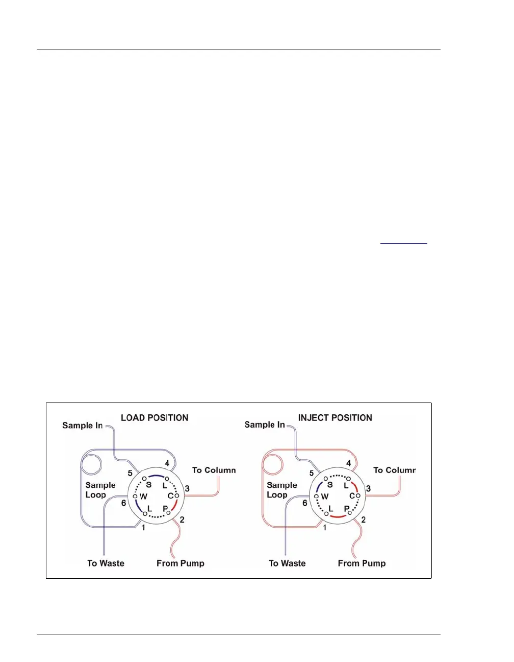
The valve has two operating positions: Load and Inject (see Figure 2-6
).
Eluent flows through either the Load or Inject path, depending on the
valve position.
• In the Load position, sample is loaded into the sample loop, where it
is held until injection. Eluent flows from the pump, through the valve,
and to the column, bypassing the sample loop. Sample flows from the
syringe or automated sampler line (if installed), through the valve,
and into the sample loop. Excess sample flows out to waste.
• In the Inject position, sample is swept to the column for analysis.
Eluent flows from the pump, through the sample loop, and on to the
column, carrying the contents of the sample loop with it.
Figure 2-6. Rheodyne Injection Valve Flow Schematics