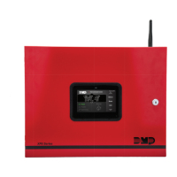
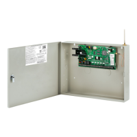
Digital Monitoring Products XF6 Series Installation and Programming Guide
10
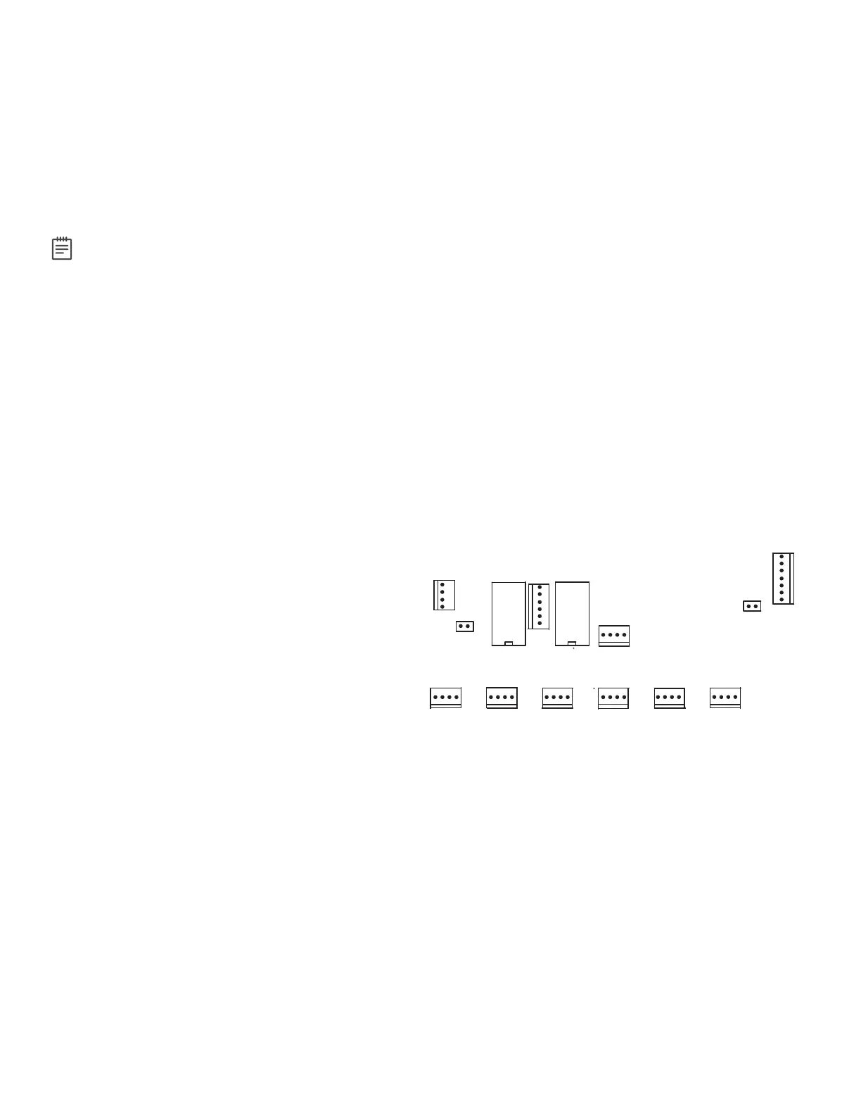
LX-BUS EXPANSION
There are five 12 VDC LX-Bus headers near the bottom of the panel:
• LX500 provides zones500-599 (XF6 Series)
• LX600 provides zones600-699 (XF6-500 Series only)
• LX700 provides zones700-799 (XF6-500 Series only)
• LX800 provides zones800-899 (XF6-500 Series only)
• LX900 provides zones900-999 (XF6-500 Series only)
Note: The XF6 does drops power to the LX-Bus during a sensor reset.
WIRELESS BUS EXPANSION
The Wireless Bus (XBUS) header provides connection for the1100X or1100XH Wireless Receiver. The XBUS provides up
to500wireless zones numbered500-999. Refer to the1100X Wireless Receiver Install Guide (LT-1822) or the1100XH
Wireless Receiver Install Guide (LT-1823) for complete information.
• XF6-100provides up to100zones
• XF6-500provides up to500zones
Wireless Bus LEDs
The two LEDs, located above the XBUS header, indicate data transmission and receipt. The left LED flashes green to
indicate the panel is transmitting data. The right LED flashes yellow to indicate the panel is receiving data.
ETHERNET CONNECTION
Description
The ETHERNET connector on the
XF6 Series Series panel allows you to connect
directly to an Ethernet network using a
standard Cat 5 cable. The ETHERNET connector
supports100Mbps full duplex operation and the
maximum impedance is100Ohms.
Ethernet LEDs
The two LEDs located on the top edge of the
connector indicate network connection. The right
Link LED (green) lights to indicate a valid receive
connection from the host network. The Activity
LED (yellow) lights when connected to a 100 Mbps
network and is o when connected to a 10 Mbps
network connection.
RESET AND TAMPER HEADERS
RESET Header
The RESET header is used to reset the panel. To reset the panel when installing the system, place the jumper across both
RESET pins before applying power to the panel. After connecting the AC and battery, remove the reset jumper.
To reset the panel while the system is operational, install the reset jumper without powering down the system. Remove
the reset jumper after one or two seconds.
After resetting the panel, begin programming within30minutes. Otherwise, you must reset the panel again to enter the
PROG menu.
TAMPER Header
The TAMPER header is designed to connect to a tamper switch with a tamper harness. One or more tamper switches can
be mounted inside the panel enclosure to supervise unauthorized removal or opening of an enclosure.
XF6 Series Panel Showing the RESET Jumper and Tamper
RESET
PROG
LX600
LX700
LX800
LX900
LX500
TAMPER
OUTPUT 1
OUTPUT 2
EXP
OUTPUTS 3-6