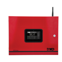
XF6 Series Installation and Programming Guide Digital Monitoring Products
11
AUX OUTPUT
Terminals5and6
Supplies positive24VDC to power alarm bells or horns. This output can be steady, pulsed, or temporal. Terminal6is
the ground reference for the aux circuit. This supervised output reads resistance of3.3kOhms or less as normal. The
indicating appliance can supply this resistance. If using a horn or siren, install the included3.3kOhm0.5W resistor
across the bell circuit to provide supervision. See the Notification Appliance section in the Compliance Listing Guide
(LT-2779) for wiring diagrams and a list of approved notification appliances.
KEYPAD BUS
Description
The panel 12 VDC Keypad Bus includes Terminals7, 8, 9, and10. You can connect up to fifteen supervised keypads and
multiple unsupervised keypads to the panel. In addition to DMP keypads, you can also connect any combination of zone
expansion modules. Refer to the specific device installation sheet for the maximum number of Keypad Bus devices. Refer
to the LX-Bus section for more information about LX-Bus expansion.
Terminal7 - RED
Supplies positive and regulated12VDC to power DMP LCD keypads and zone expansion modules. Terminal7also
supplies power for any auxiliary device. The ground reference for Terminal7is Terminal10.
The output current is shared with the smoke power output on Terminal11and zones9and10. Current draw for all
connected devices must not exceed the panel maximum current rating. See Power Supply in the Compliance Listing
Guide (LT-2779) for maximum current in a fire listed application.
Terminal8 - YELLOW
Receives data from keypads and zone expansion modules. It cannot be used for any other purpose.
Terminal9 - GREEN
Transmits data to keypads and zone expansion modules. It cannot be used for any other purpose.
Terminal10 - BLACK
The ground reference for DMP keypads, zone expansion modules, and all auxiliary devices being powered by Terminal7.
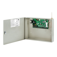
Programming (PROG) Connection
A 7830F Fire Command Keypad comes pre-installed and is connected to the programming header of the XF6 Series
panel.
OVC LEDs
The Overcurrent LED (OVC) lights red when the devices connected to the Keypad Bus and LX-Bus draw current that
exceeds the panel rating.
The LEDs turn a steady red when lit. When the OVC LEDs light red, the LX-Buses and Keypad Bus are shut down.
SMOKE OUTPUT
Terminals11and12
Supplies positive and regulated24VDC to power4-wire smoke detectors and other powered devices. This output can
be turned o by the user for5seconds using the Sensor Reset User Menu option to allow latched devices to reset.
Terminal12is the ground reference for Terminal11.
Current Rating
The Output current from Terminal11is shared with Terminals7, 25, and27.
The total current draw of all devices powered from the panel must be included with Terminal11calculations and must not
exceed the maximum output rating.
NAC CIRCUITS
Terminals13-16
Supplies two 24 VDC 2.5 Amp Class B NAC circuits. Requires 3.3k Ohm EOL resistor.