XF6 Series Installation and Programming Guide Digital Monitoring Products
3
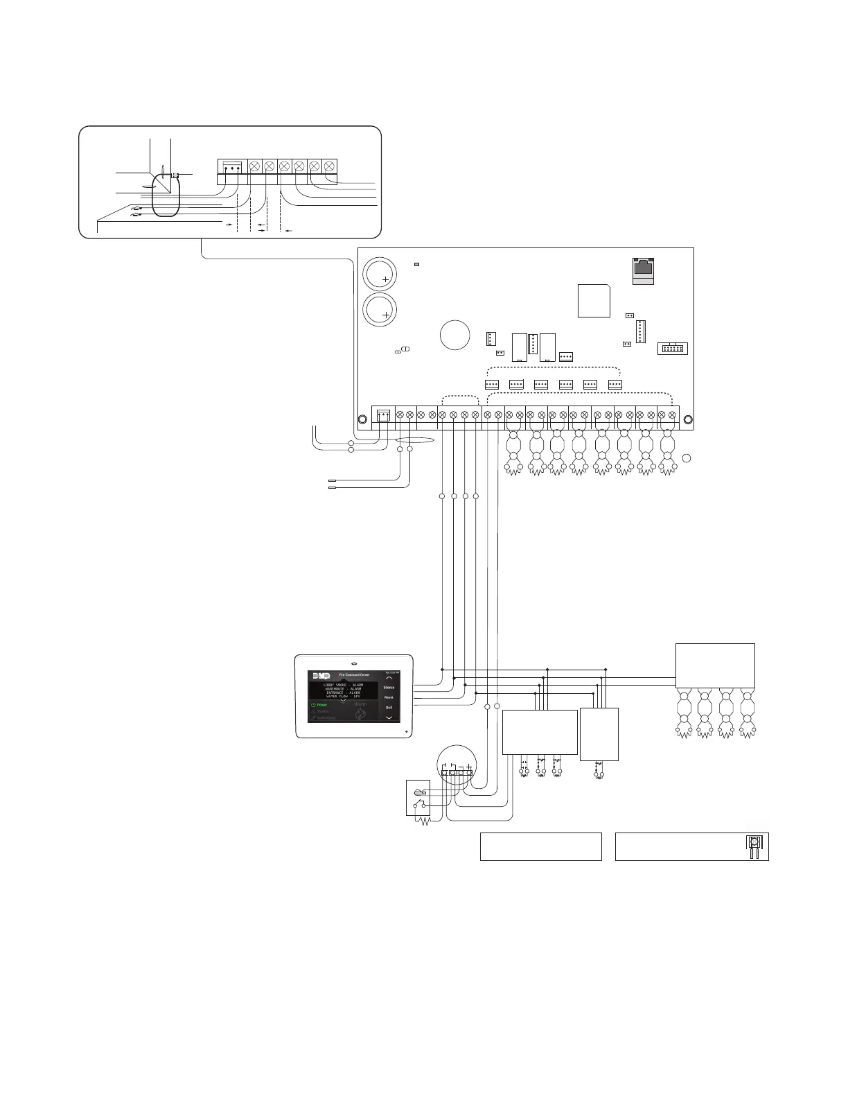
XF6 Series Wiring Diagram
WARNING: Incorrect connections
may cause damage to the unit.
Listed Resistors
10k Ohm - DMP Model 308
3.3k Ohm - DMP Model 309
1k Ohm - DMP Model 310
1k Ohm - DMP Model 311
Use Listed Power Supervision Relay
rated at 24 VDC.
Smoke
Detector
Zone Expander
Model 715
7 mA @ 12 VDC
Models 715-8, 715-16
20 mA @ 12 VDC
1k Ohm
S
= Supervised Circuit
Zone
5
Zone
6
22 gauge minimum
22 gauge minimum
22 gauge minimum
22 gauge minimum
RED
YELLOW
GREEN
BLACK
Zone Expander
Model 714
7 mA @ 12 VDC
Models 714-8, 714-16
20 mA @ 12 VDC
RED
YELLOW
GREEN
BLACK
s
s
s s s s
s
s
S S S S S S S S
S S
S SS SS S
Zone
Expander
Model 711
or 711S
7mA @ 12
VDC
1k Ohm
1k Ohm 1k Ohm
1k Ohm
RED
BLACK
Zone
1
Zone
2
Zone
3
Zone
4
All zones use 3.3k Ohm Resistors
All zones use 3.3k Ohm Resistors
AC
AC
B+
B-
AUX
GND
RED
YEL
GRN
BLK
SMK GND
NAC1+
NAC1-
NAC2+
NAC2-
Z1+
Z1-
Z2+
Z2-
Z3+
Z3-
Z4+
Z4-
Z5+
Z5-
Z6+
Z6-
Cell Module
Ethernet (Supervised)
RESET
LOAD
PROG
LX600
LX700
LX800
LX900
LX500
BAT T
STA RT
TAMPER
OUTPUT 1
OUTPUT 2
1100 WIRELESS XBUS
(Supervised)
EXP
XF6 Series Panel
To pre-installed 130 VA power
supply
Connect to 120V 60 Hz circuit
with 1.3 Amp not controlled
by switch
24 VDC Connections
12 VDC Connections (Supervised)
The XF6-100 only
contains one
LX-Bus connection
3.3k Ohm EOL
FOR FUTURE USE
12 VDC Connection
NAC
1
NAC
2
s
s
s
s
s
s
s
s
s
s
s
s
s
s
s
s
s
s
PWR
Maximum impedance is 100 Ohmns
LINK LED
ACTIVITY LED
Use Model 305 Relay
for Outputs 1 and 2
CAUTION: DO NOT USE LOOPED WIRE UNDER
TERMINALS. BREAK WIRE RUN TO PROVIDE
SUPERVISION OF CONNECTIONS.
Using verification
delays is optional. Use
the delays marked on
the smoke detectors.
Wiring on terminals 7 through 16 must exit right and maintain 1/4"
separation from the Battery and Auxiliary wiring.
Intended Installation Environment - Indoor/Dry
All Circuits (Class B):
Impedance value for testing at
which open circuit faults, short
circuit faults, and ground faults
prevent normal operation.
Open - Infinite
Shorts - 0.1 Ohms
Ground - 0.1 Ohms
7830F Keypad
Outputs 3-6
To 24 VDC battery
LX and Keypad Bus:
Use one bus per notification
area (zone)
¼"
¼"
AC AC B+
B-
AUX GND RED YEL
Nominal circuit voltage 24 VDC
Maximum short circuit current 62mA
SYSTEM COMPONENTS
The diagram below shows some of the accessory modules you can connect for use in various applications. A brief
description of each module follows in the Ordering Information section.
28 VAC 130 VA wire-in
transformer
Maximum 12/24VDC output
per circuit (Cannot exceed
3.5 amps combined output)
24 VDC Circuits:
• NAC 1 - 2.5 A
• NAC 2 - 2.5 A
• Battery Charging - 1.5 A
• SMK/AUX - .75 A
(Special Application)
12 VDC Circuits
• Keypad - 1 A
• LX-Bus - .70 A each
• X-Bus - .7 A each
NAC Circuit:
Supervised, Power Limited
Battery Backup
Regulated 0.25A
Special Application 2.5A
Maximum Line Loss 2V
Smoke/Auxiliary Power:
Supervised (Ground Only),
Power Limited
Battery Backup
24 VDC nominal rated
voltage
Form C Relays
Programmable
3.0 VDC, 1 A, 0.35 power
factor, Resistive, Power
Limited
All circuits are inherent
Power Limited except the
red battery wire and AC
terminal.
Open Collector Outputs 3-6,
Programmable
12V 30mA
The open collector output
must be connected to
devices located within the
same room as the panel.
LIGHTNING PROTECTION
Metal Oxide Varistors and Transient Voltage Suppressors help protect against voltage surges on panel input and output
circuits. Additional surge protection is available with Model370or370RJ Lightning Suppressors. For more information,
refer to the 370/370RJ Installation Sheet (LT-0181).