Dobot CR A Series User Guide
Issue V1.3 (2023-09-14) User Guide Copyright © Yuejiang Technology Co., Ltd.
57
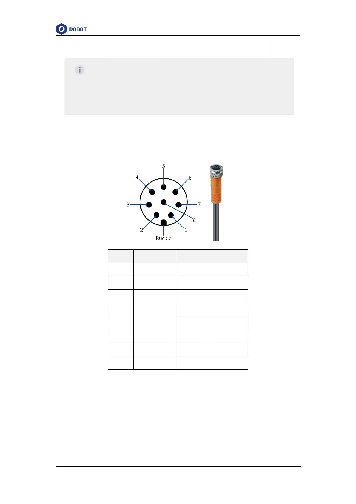
The cable used in the tool I/O is the cable specified by Dobot (model: SIGNAL 120108-06-
014 (CR20A) / Lutronic FP-222460 (other CR A models)). The pin distribution and cable definition
of the plug are shown as follows.
Digital input/output:
The tool digital input is PNP type. The wiring of connecting external simple switch circuit is
shown below.
NOTE
For CR20A, the X1 aviation socket pins are defined as shown above, and the
AI/DI/DO of the X2 aviation socket are numbered consecutively after X1. For
example, DI1 of X2 is DI3 and DI2 of X2 is DI4, and similarly for the cable pins
below.