60
WN 059677 45532 - 11/2023
ES 250 PRO/ES 250 PRO FST
ES 400 PRO/ES 400 PRO FST
Mounting instructions
7.3.1 Service Mode
In ServiceMode1, the sensors are not evaluated by the control unit.
In ServiceMode2, the CAN components are not evaluated by the control unit.
If a ServiceMode is activated, all errors are acknowledged and the closing
movements run at crawl speed.
Display
1. Plug in the mains plug to the power supply unit
2. If present, connect the battery.
The control unit carries out a self-test.
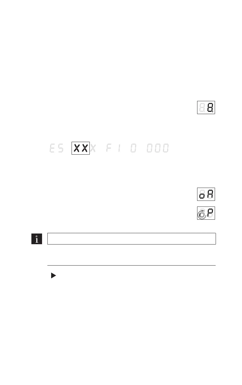
The device detection is shown on the 2-digit display. "ES"
followed by the "control unit" (represented byXXX) and the
"firmware version".
Control unit:
FST = escape route control unit
STd = standard control unit
The CAN BUS is initialized.
The small, spinning “o” and the “P” show that parametrization
is required.
The control unit switches to Service Mode 2.
Note
If a CAN synchronization cable is used, replace steps 3-7 with the
commissioning instructions for the CAN synchronization cable.
3. Press for 3 seconds to open the parameters menu.
4. Set the parameters “L1”, “dL” and “Pr”, see “11 Parameterization”.
5. If a mechanical operating mode switch is used, set the parameter
“PS” to the value 0.