15 | Examples of settings
D-ISC 100 x xx2
159
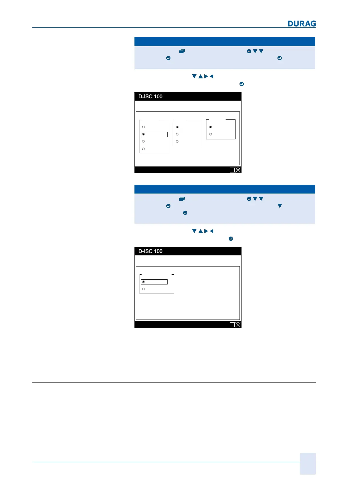
D‑ISC100 menu path:
Standard display System setup (menu3) DURAG Modbus
(menu3.3))
Communication parameters (menu3.3.1)
=Communication parameters MENU 3.3.1
Use the arrow keys (
) to set the displayed values, and
save them by pressing the Enter key (
):
Menu: 3.3.1
Status: S1.3:Normal measurement
Communication parameter
Baudrate Parity
9600
19200
38400
None
Even
Stop Bits
1 Bit
2 Bits
Odd
57600
E
Fig.15.2: Communication parameters menu 3.3.1
D‑ISC100 menu path:
Standard display System setup (menu3) DURAG Modbus
(menu3.3))
Communication parameters (menu3.3.1) Bus termin-
ation (menü3.3.2)
=Bus termination MENU 3.3.2
Use the arrow keys (
) to set the displayed value, and
save it by pressing the Enter key (
):
Menu: 3.3.2
Status: S1.3:Normal measurement
Bus parameter
Bus-Termination
Active
Inactive
E
Fig.15.3: Bus parameters menu 3.3.2
Make sure that the connected devices also have the necessary
settings.
15.4 Example: Clearing the PIN protection (logging
in)
For the individual steps, proceed in accordance with the
D‑ISC100 menu path (for an explanation of this, see Section7.1
Navigation guide within this manual [}79]). Comments on the
settings are included in the appropriate text where necessary.
 Loading...