15 | Examples of settings
D-ISC 100 x xx2
177
After the analogue output has been set, the signal range (15.10.1
Example: Setting the signal range [}177]) for the analogue output
must then be defined.
15.10.1 Example: Setting the signal range
Fig.15.36: Analogue output, specific parameter
General points regarding the signal range
The D‑ISC100 provides two output ranges for each analogue
output. As a rule, it is sufficient to specify
one
output range within
the signal range for the measured value of the assigned sensor.
In order to ensure that the measured value outputs from the
control cycles of the sensor also lie securely within the output
range, for example, the signal ranges of the sensor and of the
Universal control unit (analogue output) must be set to identical
values.
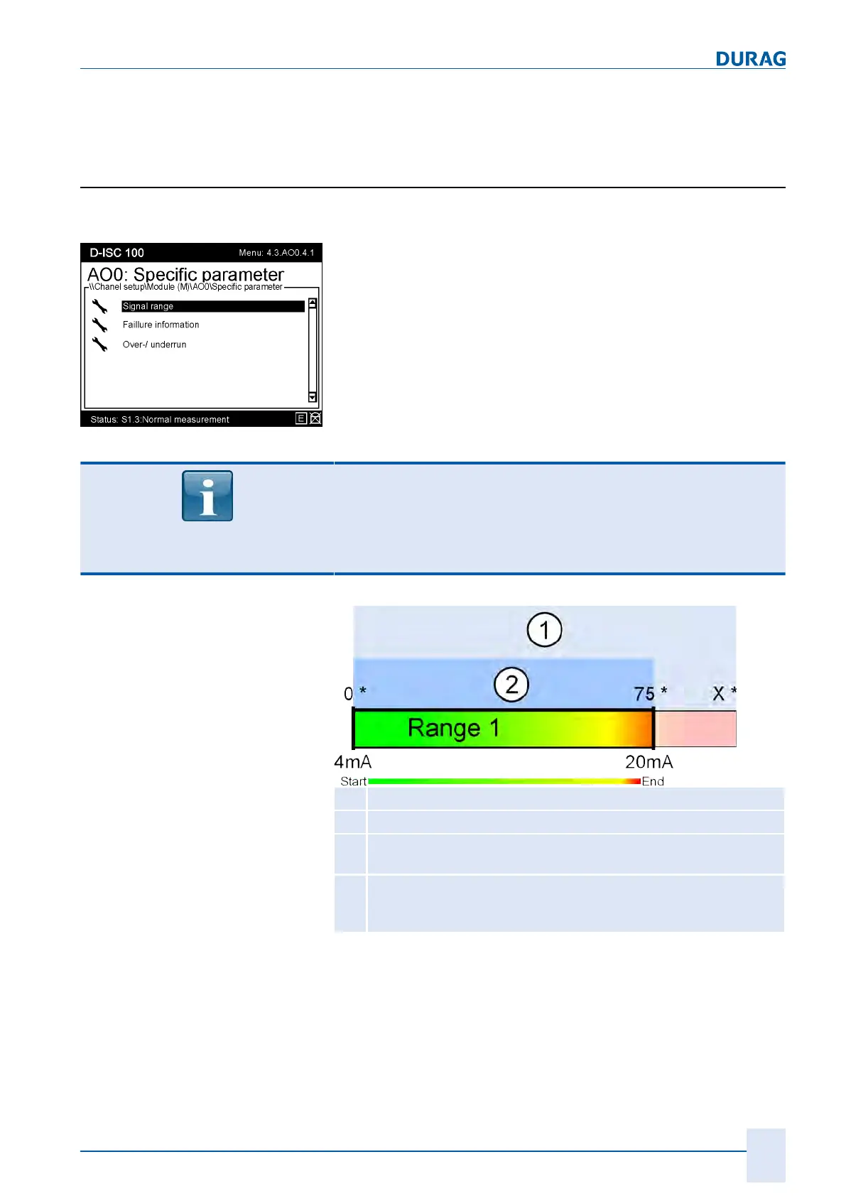
Exclusive use of signal range 1
1
Maximum signal range * (signal range [}204] )
2
Adjusted output range (here 75 *, possible setting 0 … x *)
dependent upon the sensor
*
(e.g. %OP, scattered light, extinction, %transmission, gas velo-
city)
dependent upon the sensor
Fig.15.37: Ranges
In special cases a second output range may also be specified for
a measured value. If a specified value is exceeded in the first
output range, the D‑ISC100 changes over to the second output
range. If the current measured value then falls below another
previously specified value, the D‑ISC100 will switch back to the
first output range.

 Loading...