15 | Examples of settings
192
D-ISC 100 x xx2
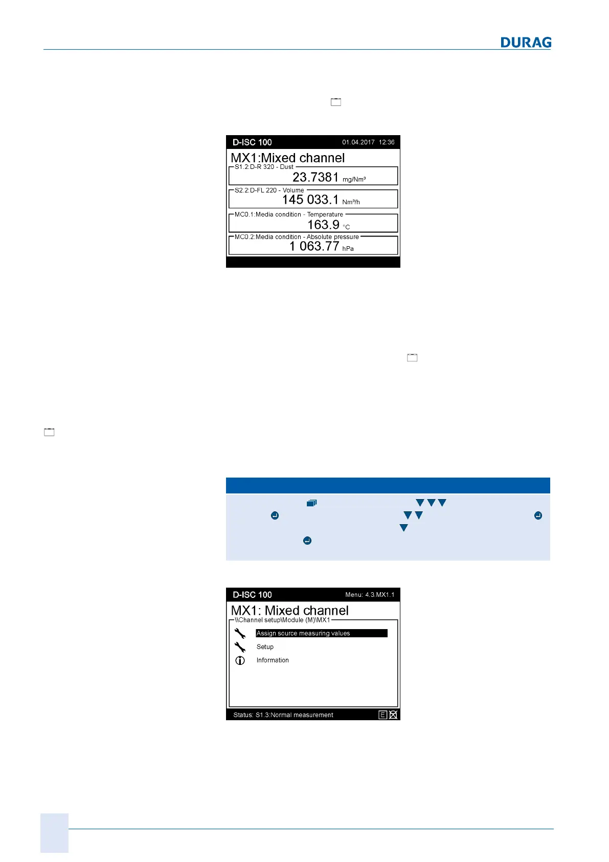
If the measured variables of different sensors/modules are simul-
taneously required in a measurement display, this can be
achieved using the ["
Mixed channel"] software module.
See also Section 10.4.1.4 [Mixed channel] (MX1...2) [}116].
Fig.15.63: Measurement display in the mixed channel
Requirement:
● The sources used (sensors/modules) are already configured
for a measured display in the Universal operation unit. See
also 15.8 Examples: Parameterising sensors [}167] et. seq.
● The mixed channel module must be enabled (see Section
10.4.1.3 Enable/disable modules [}116]).
● For step 6, the software module [
media condition] may
need to be configured and enabled (see Section 15.16 Ex-
ample: Configuring the Media condition software module
[}200]).
Configuring the mixed
channel module
Step1
Access the menu for the mixed channel:
D‑ISC100 menu path:
Standard display User mode (menu1) Channelsetup
(menu4)
D−ISC100 (D) (menu4.1) Modules (M) (menu4.3)
Software modules (Menü 4.3.1) (z.B. …) Mixed channel internal
(menu 4.3.MX1)
=MENU 4.3.MX1.1
Fig.15.64: Assign source measuring value I
 Loading...